20
INSTRUCTIONS FOR MECHANICS
Observe the SAFETY RULES when ma-
king adjustments!
Before adjusting the machine remove the face cover and
the finger guard left on the machine head, the upper feed
dog, the presser foot, the cloth plate with hinge plate and
throat plate, the feed dog, the throat plate support with
front needle guard and the rear needle guard.
Insert a new needle!
Refer to paragraph
CHANGING THE NEEDLE
in section
OPERATING INSTRUCTIONS.
SETTING THE LOWER LOOPER
1.
Styles 81500A, B, B1H, B2, BA, BA1H, BA2 and
81500C
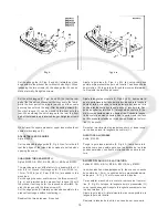
The lower looper (A, Fig. 7) of these styles has two
offset flats on its shank for adjusting the looper re-
spectively the looper point with respect to the needle.
Insert the lower looper (A) into the rear hole of looper
lever (B). Now snug the set screw (C) at the back of
the looper lever against the flat on the looper shank
(E) so that the point of the lower looper passes as
close as possible to the spot on the back of the needle
(N), without deflecting it. Now tighten the second screw
(D) firmly.
1.1. Rotate handwheel in operating direction until the
needle just starts from its lowest position moving
upward. In this position the distance between the point
of the looper and the center of the needle should be
12 mm (15/32 in.) (see Fig. 8).
If adjustment is necessary loosen nut (G, Fig. 7) and
move the ball stud (H) of ball joint (J) in the slot of
looper lever (B) accordingly until the distance of 11
mm (7/16 in.) is reached. Retighten nut (G).
2.
Style 81500E
The lower spreader (A, Fig. 7 A) of this style has only
one seat on its shank.
Insert the lower spreader (A, Fig. 7 A) into the rear
hole of looper lever (B). Tighten screw (D) on the seat
of the lower spreader shank, then tighten set screw
(C).
The point of the lower spreader must pass as close
as possible to the spot on the back of the needle (N),
without deflecting it.
If adjustment is necessary loosen set screws (K, Fig.
7 A) and move looper lever (B) on its cone shaft
accordingly. Retighten set screws (K).
The distance of 11 mm (7/16 in.) (see Fig. 8 A)
between the point of spreader and the center of the
needle is set as described in item 1.1.
INSTRUCCIONES PARA MECANICOS
Preste atención a las REGLAS DE SEGURI-
DAD mientras realiza ajustes!
Antes de realizar ajustes en la máquina, quite la tapa frontal y
el protector de dedos, el diente alimentador superior, el pie
prensatelas, la plancha de tela con la plancha articulada y la
plancha de aguja, el diente alimentador, el soporte de la plan-
cha de aguja y los guarda aguja delantero y trasero.
Coloque una nueva aguja!
Refiérase al parágrafo
CAMBIO DE AGUJA
en la sección
INS-
TRUCCIONES DE OPERACION.
AJUSTE DEL LOOPER INFERIOR
1.
Estilos 81500A, B, B1H, B2, BA, BA1H, BA2 y 81500C
El looper inferior (A, Fig. 7) en estos estilos de máquinas
tienen dos superficies planas en su cuello para ajustar
adecuadamente el looper con respecto a la aguja.
Inserte el looper inferior (A) en el hueco posterior de la
leva del looper (B). Sujete el tornillo de sujeción (C) en la
parte trasera de la leva del looper contra la parte plana
del cuello del looper (E) para que la punta del looper
inferior pase lo mas cerca posible al rebajo en la parte
trasera de la aguja (N) sin desviarla. Apriete el segundo
tornillo (D) ahora.
1.1
Gire el volante en sentido de operación hasta que la agu-
ja quede en su posición mas baja antes de moverse ha-
cia arriba. En este punto, la distancia entre la punta del
looper y el centro de la aguja debe ser de 12 mm (Ver
Fig. 8).
De ser necesario algún ajuste adicional, suelte la tuerca
(G, Fig. 7) y mueva el perno de bola (H) de la articula-
ción esférica (J) en la ranura de la leva del looper (B)
hasta que alcance una distancia de 11 mm.
Apriete la tuerca (G) nuevamente.
2.
Estilo 81500E
El spreader inferior (A, Fig. 7 A) en este estilo de má-
quina tiene 1 sola superficie plana en su cuello.
Inserte el spreader inferior (A, Fig. 7 A) en el hueco
posterior de la leva del looper (B). Ajuste el tornillo (D)
en la parte plana del cuello del spreader, luego apriete
el tornillo de sujeción (C).
La punta del spreader inferior debe pasar lo más cerca
posible a la rebaja en la parte trasera de la aguja (N) sin
desplazarlo.
De ser necesario realizar algún ajuste, suelte los torni-
llos de sujeción (K, Fig. 7A) y mueva la leva del looper
(B) en su eje cónico adecuadamente. Apriete los tornillos
de sujeción (K).
La distancia de 11 mm (Ver Fig. 8 A) entre la punta del
spreader y el centro de la aguja se ajusta como está
descrito en el punto 1.1.
Содержание 81500A
Страница 8: ...8 INSTALLATION INSTALACION ...
Страница 10: ...10 ...
Страница 21: ...21 ...
Страница 23: ...23 Fig 10 Fig 11 Fig 11 A Fig 11 B Fig 11 C Fig 12 ...
Страница 25: ...25 ...
Страница 28: ...28 ...
Страница 33: ...33 VIEWS AND DESCRIPTION OF PARTS VISTAS Y DESCRIPCIONES DE LAS PARTES Y PIEZAS ...
Страница 34: ...34 ...
Страница 36: ...36 ...
Страница 38: ...38 ...
Страница 40: ...40 ...
Страница 42: ...42 ...
Страница 44: ...44 ...
Страница 46: ...46 ...
Страница 48: ...48 ...
Страница 50: ...50 ...
Страница 52: ...52 ...
Страница 54: ...54 ...
Страница 56: ...56 ...
Страница 58: ...58 ...
Страница 60: ...60 ...
Страница 62: ...62 ...
Страница 64: ...64 ...
Страница 68: ......

