


9
ADJUSTING INSTRUCTIONS
NOTE:
Instructions stating direction or location, such as
right, left, front or rear of machine, are given relative
to mechanic's position in front of the machine, when
the machine is placed on an adjusting table, with
the pulley to the right and the needle bar in vertical
position. The pulley rotates clockwise, in operating
direction; when viewed from the right end of the
machine.
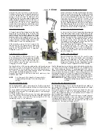
INSERTING THE NEEDLE
Before adjusting the machine, insert a new needle with the
shank as far as possible into the needle bar. The long needle
groove must point to the front (toward the operator). Tighten
the needle clamp nut securely. Use the single ended open
jaw wrench part No. 21388 from the accessories of the
machine.
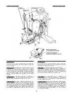
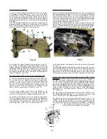
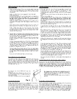
SETTING THE LOOPER
Remove the presser foot, throat plate and feed dog and on
styles 80800HN and HAN also the needle guard for
convenient access to the machine. On styles 80800CN, DN
and EN loosen the screw (A, Fig. 3) in the feed bar (B) and
push the feed bar needle guard (C) to the rear to avoid its
contacting the needle (D).
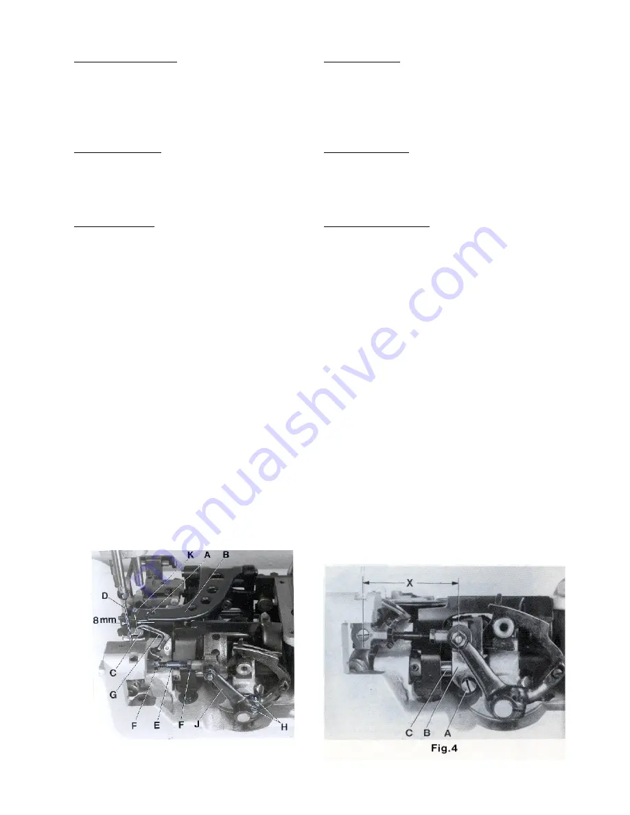
For the two thread double locked stitch styles 80800CN, EN,
HN and HAN, set the looper connecting rod (E) so the
distance (X, Fig. 4) between the center lines of the two ball
joints is 69.8 mm (2 3/4"). The dimension (X, Fig. 4) should be
68.3 mm ( 2 11/16) on the single thread chain stitch style
80800DN. For adjustment loosen the two nuts (F, Fig. 3) and
turn connecting rod (E) forward or backward as required
to obtain specified dimension, retighten nuts (F).
NOTE:
The left nut has a left hand thread.
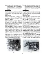
Set the looper (G) so the distance from the centerl ine of the
needle (D) to the looper (G) is 8 mm (5/16") when the looper
is at its farthest position to the right. Looper gauge No. 21225-
5/16 can be used advantageously in making this adjustment.
For adjustment loosen screws (H) in the looper drive lever (J),
reposition as required to obtain specified dimension and
retighten screws (H) assuring that all end play is taken out of
the looper drive lever rocker shaft. Check to insure a
clearance of approx. 1 mm (.040") between the point of the
looper and the bed end cover when the looper is at its extre-
me left position. Should the looper strike the bed end cover,
recheck the distance between center lines of ball joints and
the looper gauge distance as described above.
Rotate the machine pulley in operating direction so that the
looper moves from right to left. The looper point should pass
as close as possible to the back of the needle without
contacting 0.08 to 0.13 mm (.003 to .005") clearance. For
adjustment loosen screws (A, Fig. 4) in the looper eccentric
fork (B) and turn looper rocker shaft (C) on the looper rocker
forward or backward as required. Retighten screw (A).
EINSTELLANLEITUNG
BEACHTEN SIE:
Hinweise auf Richtung und Lage, wie rechts, links,
vorne oder hinten beziehen sich auf die Sicht vom Platz
des sich vor der Maschine befindlichen Mechanikers aus,
wenn die Maschine auf einem Einnähtisch steht, mit dem
Handrad nach rechts und mit senkrecht stehender Nadel-
stange. Die Riemenscheibe dreht sich im Uhrzeigersinn in
Nährichtung, vom rechten Ende der Maschine aus ge-
sehen.
EINSETZEN DER NADEL
Vor dem Einstellen der Maschine muß eine neue Nadel so ein-
gesetzt werden, daß der Nadelkolben oben in der Nadelstange
anstößt und die lange Rinne der Nadel nach vorne (zur
Bedienungsperson) zeigt. Ziehen Sie die Nadel-Klemmmutter gut
an. Verwenden Sie den Einmaulschlüssel Teil Nr. 21388 aus dem
Maschinen-Zubehör.
EINSTELLUNG DES GREIFERS
Zur bequemeren Einstellung entfernen Sie Drückerfuß, Stichplatte
und Transporteur und bei den Maschinen 80800HN und HAN
auch den Nadelanschlag. Lösen Sie bei den Maschinen
80800CN, DN und EN die Schraube (A. Fig. 3) im Transporteur-
träger (B) und drücken Sie den Nadelanschlag nach hinten,
damit er die Nadel (D) nicht berühren kann.
Bei den Zweifaden-Doppelkettenstichmaschinen Typen
80800CN, EN, HN und HAN muß die Greiferverbindungsstange
(E) so eingestellt sein, daß der Abstand (X, Fig. 4) von der Mitte
zu Mitte Kugelgelenk 69,8 mm beträgt. Bei der Einfaden-Ein-
fachkettenstichmaschine Typ 80800DN beträgt der Abstand
(X, Fig. 4) 68,3 mm. Zum Einstellen lösen Sie die beiden Muttern
(F, Fig. 3) und drehen die Verbindungsstange (E) vor oder zu-
rück bis der erforderliche Abstand erreicht ist. Ziehen Sie die
Muttern (F) wieder an.
BEACHTEN SIE:
Die linke Mutter hat ein Linksgewinde.
Stellen Sie den Greifer (G) so, daß der Abstand von Mitte Nadel
(D) bis zur Spitze des Greifers (G) 8 mm beträgt, wenn der Greifer
in seiner rechten Endstellung ist. Die Greifereinstelllehre Nr. 21225-
5/16 erleichtert diese Einstellung. Zur Einstellung lösen Sie die
Schrauben (H) im Greiferantriebshebel (J) und verdrehen die-
sen entsprechend, bis der erforderliche Abstand erreicht ist. Zie-
hen Sie die Schrauben (H) wieder an und achten Sie darauf,
daß die Greiferantriebshebelwelle kein Spiel hat. Prüfen Sie, ob
zwischen Greiferspitze und Abschlußblech ein Abstand von etwa
1 mm ist, wenn der Greifer in seiner äußerst linken Endstellung ist.
Sollte der Greifer gegen das Abschlußblech schlagen, muß der
Abstand von Mitte zu Mitte Kugelgelenk sowie der Greiferab-
stand, wie oben beschrieben, überprüft werden.
Drehen Sie die Riemenscheibe in Nährichtung so, daß sich der
Greifer von rechts nach links bewegt. Die Greiferspitze soll so dicht
wie möglich hinter der Nadel vorbeigehen, ohne diese zu be-
rühren (0,08 bis 0,13 mm Abstand). Zur Einstellung lösen Sie die
Schraube (A, Fig. 4) in der Greiferexzentergabel (B) und schwen-
ken die Greiferhebelwelle (C) am Greiferhebel mit Greifer nach
Bedarf vor oder zurück. Ziehen Sie die Schraube (A) wieder an.
Fig. 3
Содержание 80800
Страница 14: ...14...
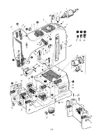
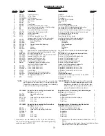
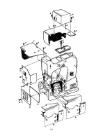
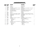
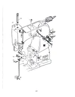
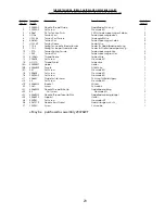
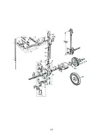
Страница 17: ...17 EXPLODED VIEWS AND DESCRIPTION OF PARTS EXPLOSIONSZEICHNUNGEN UND TEILEBESCHREIBUNGEN...
Страница 18: ...18...
Страница 20: ...20...
Страница 22: ...22...
Страница 24: ...24...
Страница 26: ...26 1 16a...
Страница 28: ...28...
Страница 30: ...30 Add Loctite 262 CE66 Add Loctite 262 CE66...
Страница 32: ...32...
Страница 34: ...34...
Страница 36: ...36...
Страница 38: ...38...
Страница 40: ...40...