


12
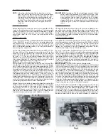
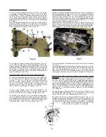
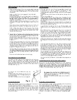
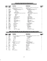
LOOPER THREAD TAKE-UP
On the two thread double locked stitch styles, the height
of the looper thread take-up (A, Fig. 11) is set so, that the
cast-off hook (C) forces the looper thread over the corner
(B) of the looper thread take-up (A) at the time the point
of the descending needle is flush with the lower edge at
looper or projects up to 1 mm (.040") below the lower edge
of looper.
Draw the looper thread into the machine, rotate pulley in
operating direction and note the position of the needle
point to lower edge of looper at the time the cast-off (C)
forces the looper thread over the corner (B).
For setting the looper thread take-up loosen screw (D,
Fig. 11)When needle point is positioned above the lower
edge of looper, the looper thread take-up (A) has to be
raised accordingly. When the needle point is positioned
more than 1 mm (.040") below the lower edge of looper,
the looper thread take-up (A) has to be lowered accor-
dingly. Retighten screw (D).
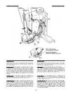
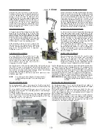
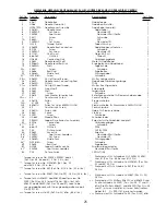
SETTING NEEDLE THREAD TAKE-UP ROLLER AND EYELET
On the two thread double locked stitch styles 80800CN,
EN, HN and HAN, the height of the needle thread take-
up roller (C, Fig. 10) is set so that the needle thread on
the downstroke of the needle just contacts the roll at
the time the needle thread loop is released from the
looper. Loosen screw (D) and set the needle thread
take-up roller accordingly. Retighten screw (D).
On the single thread chain stitch style 80800DN the
needle thread take-up roller (C) should be positioned
so as not to contact the needle thread at any time.
On all styles the eyelet (E, Fig. 10) should be positioned so,
that the needle thread runs nearly horizontal, parallel to
cloth plate, between eyelet (G) on needle bar connection
and eyelet (E) on machine arm, when the needle is in its
upmost position. Eyelet (E) is secured by screw (F).
GREIFERFADENAUFNEHMER
Bei den Zweifaden-Doppelkettenstichmaschinen wird die Höhe
des Greiferfadenaufnehmers (A, Fig. 11) so eingestellt, daß der
Greiferfadenabzugshaken (C) den Greiferfaden zu dem
Zeitpunkt über die Ecke (B) am Greiferfadenaufnehmer (A)
zieht, wenn die Spitze der sich nach unten bewegenden Nadel
mit der Unterkante des Greifers bündig ist oder bis zu 1 mm
unterhalb der Greiferunterkante steht.
Fädeln Sie den Greiferfaden ein, drehen Sie die Riemenschei-
be in Nährichtung und merken Sie sich die Stellung der Nadel-
spitze zur Greiferunterkante zum Zeitpunkt wo der Greiferfaden-
abzugshaken (C) den Greiferfaden über die Ecke (B) zieht.
Zur Einstellung des Greiferaufnehmers lösen Sie die Schraube
(D, Fig. 11).
Steht die Nadelspitze oberhalb der Greiferunterkante muß der
Greiferfadenaufnehmer (A) entsprechend höher gestellt wer-
den. Steht die Nadelspitze mehr als 1 mm unter der Greifer-
unterkante, muß der Greiferfadenaufnehmer entsprechend
tiefer gestellt werden. Ziehen Sie die Schraube (D) wieder an.
EINSTELLUNG DER NADELFADENABZUGSROLLE UND FADEN-
FÜHRUNG
Bei den Zweifaden-Doppelkettenstichmaschinen 80800CN,
EN, HN und HAN wird die Höhe der Nadelfadenabzugsrolle
(C, Fig. 10) so eingestellt, daß der Nadelfaden beim Nieder-
gehen der Nadel die Rolle zu dem Zeitpunkt gerade berührt,
wenn die Nadelfadenschlinge vom Greifer freigegeben wird.
Lösen Sie die Schraube (D) und stellen Sie die Nadelfaden-
abzugsrolle (C) entsprechend ein. Ziehen Sie die Schraube
(D) wieder an.
Bei der Einfaden-Einfachkettenstichmaschine 80800DN muß
die Nadelfadenabzugsrolle (C) so eingestellt werden, daß
sie auf keinen Fall vom Nadelfaden berührt wird.
Bei allen Maschinen wird die Fadenführung (E, Fig. 10) so
eingestellt, daß der Nadelfaden zwischen der Fadenführung
(G) am Nadelstangenmitnehmer und der Fadenführung (E)
am Maschinenarm etwa waagrecht, parallel zur Stoffplatte
verläuft, wenn die Nadel in der obersten Stellung ist. Die
Fadenführung (E) wird mit der Schraube (F) befestigt.
Содержание 80800
Страница 14: ...14...
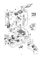
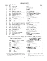
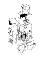
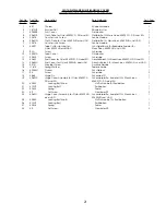
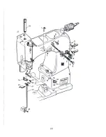
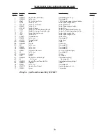
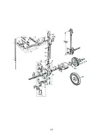
Страница 17: ...17 EXPLODED VIEWS AND DESCRIPTION OF PARTS EXPLOSIONSZEICHNUNGEN UND TEILEBESCHREIBUNGEN...
Страница 18: ...18...
Страница 20: ...20...
Страница 22: ...22...
Страница 24: ...24...
Страница 26: ...26 1 16a...
Страница 28: ...28...
Страница 30: ...30 Add Loctite 262 CE66 Add Loctite 262 CE66...
Страница 32: ...32...
Страница 34: ...34...
Страница 36: ...36...
Страница 38: ...38...
Страница 40: ...40...