3: Installation
3-8
UPS453-01-00 MINIpowerPLUS User Manual Dated 08-03-12
3.3.3 Connect the UPS input/output power cables
The UPS input and output cables are fitted to a single power connector that plugs into a receptacle located
on the rear UPS cabinet wall. A ready-made connector complete with cable is provided with the equipment.
The supplied cable is approximately 600mm
in length and terminated with an input plug and outlet socket
suitable for the UPS capacity rating. Where the supplied cable length is inadequate for a particular installation
it can be replaced by a longer cable following the instructions contained at the end of this section.
Note:
If the UPS connector is fitted with a maintenance bypass switch refer to the Options chapter in this
manual for details (See paragraph 7.1).
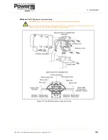
MINIpowerPLUS 5000 power cables
A cable with a maximum capacity of 16A is supplied with the MINIpowerPLUS 5000. For applications where
the anticipated UPS input current exceeds 13A (e.g. 5000 VA with Vin=184V)
we recommend that the UPS
input power cable is connected directly to the electrical distribution control panel. If this requires a longer
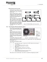
power cable the connector can be rewired as shown below in Figure 3.9.
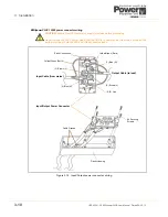
MINIpowerPLUS 10000 power cables
A ready-made cable of approximately 600mm
in length, fitted with standard IEC connectors, is supplied with
the UPS. If it is necessary to rewire the connector the cable must be a minimum of 4mm² and have insulated
wires – see Figure 3.10.
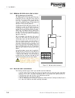
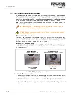
Figure 3.8 UPS input/output power receptacles
Connecting the UPS power connector
1.
Connect the UPS input/output power connector assembly to the power receptacle on the rear of the UPS
and secure in place using two screws, as shown in Figure 3.8.
2.
Check that all the UPS loads are turned OFF then connect the UPS output cable to the load distribution
point.
3.
Connect the UPS input mains supply cable to a power outlet adequate for the voltage and current
required.
Key Point:
A link is fitted in the power connector which ensures that the UPS cannot be started
unless the connector is plugged-in to the UPS power receptacle.
CAUTION: Before proceeding, either ensure that the UPS input power cable is disconnected from
the mains supply or, if the cable is connected directly to the mains, ensure that the mains supply is
isolated at the distribution point.
Power Receptacle
& Input Fuse
Power Receptacle
& Input Fuse
MINIpowerPLUS 10000
5000/2, 6250/2, 7500/2, 8750/2 & 10000/2
MINIpowerPLUS 5000
1250, 2500, 3750 & 5000
Содержание Minipower Plus Rack
Страница 1: ...Pioneering solutions for total power protection MINIpower PLUS User Manual ...
Страница 2: ......
Страница 8: ...1 Safety 1 2 UPS453 01 00 MINIpowerPLUS User Manual Dated 08 03 12 ...
Страница 26: ...3 Installation 3 12 UPS453 01 00 MINIpowerPLUS User Manual Dated 08 03 12 ...
Страница 40: ...5 Maintenance 5 2 UPS453 01 00 MINIpowerPLUS User Manual Dated 08 03 12 ...
Страница 42: ...6 Troubleshooting 6 2 UPS453 01 00 MINIpowerPLUS User Manual Dated 08 03 12 ...


