C.I.B. UNIGAS - M039207CB
4
GENERAL FEATURES
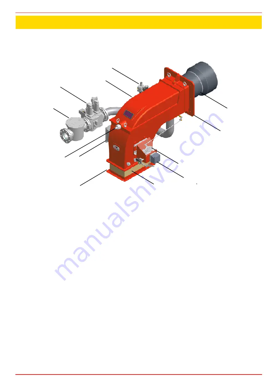
This series of industrial burners is designed for all those applications that require big-sized air fans or air-flue heat exchangers to be
installed in sound-proof areas to reduce noise. They can be provided with built-in or separately-mounted control panel (console or wall-
mounted).
Fig. 1
1
Adjusting cam
2
Actuator
3
Bellows
4
Air inlet flange
5
Junction box
6
Combustion head adjusting screw
7
Gas filter
8
Gas valves group
9
Cover
10 Ignitor gas train
11 Combustion head-blast tube group
12 Burner flange
Gas operation:
the gas coming from the supply line, passes through the valves group provided with filter and stabiliser. This one for-
ces the pressure in the utilisation limits. The actuator (2) moves proportionally the air damper and the gas butterfly valve It drives an
adjusting cam (13) with variable shape. This one allows the optimisation of the gas flue values, as to get an efficient combustion.
Heavy oil operation:
the fuel coming from the supply line, is pushed by the pump to the nozzle and then into the combustion chamber,
where the mixture between fuel and air takes place and consequently the flame.
In the burners, the mixture bertween fuel and air, to perform clean and efficient combustion, is activated by atomisation of oil into very
small particles. This process is achieved making pressurised oil passing through the nozzle.
The pump main function is to transfer oil from the tank to the nozzle in the desired quantity and pressure. To adjust this pressure,
pumps are provided with a pressure regulator (except for some models for which a separate regulating valve is provided). Other pumps
are provided with two pressure governors: one for the high and one for low pressure (in double-stage systems with one nozzle).
The adjustable combustion head can improve the burner performance. The combustion head determines the energetic quality and the
geometry of the flame. Fuel and comburent are routed into separated ways as far as the zone of flame generation (combustion cham-
ber).
PART I: INSTALLATION MANUAL
8
12
5
7
6
4
3
2
1
11
9
10
Содержание KTP1030
Страница 24: ...C I B UNIGAS M039207CB 24 HYDRAULIC DIAGRAMS Fig 16 Hydraulic diagram 3ID0023 Single burner configuration...
Страница 25: ...C I B UNIGAS M039207CB 25 Fig 17 Hydraulic diagram 3ID0014 Two or more burners configuration...
Страница 46: ...C I B UNIGAS M039207CB 46...
Страница 47: ...C I B UNIGAS M039207CB 47...
Страница 48: ...C I B UNIGAS M039207CB 48...
Страница 49: ...C I B UNIGAS M039207CB 49...
Страница 50: ...C I B UNIGAS M039207CB 50 Pumping Unit Electric Wiring Diagrams...
Страница 51: ...C I B UNIGAS M039207CB 51...
Страница 52: ...C I B UNIGAS M039207CB 52...
Страница 55: ...C I B UNIGAS M039207CB 55...
Страница 59: ......
Страница 74: ......
Страница 83: ......
Страница 84: ......
Страница 85: ...RWF50 2x RWF50 3x User manual M12922CB Rel 1 0 07 2012...
Страница 100: ...16 Note Specifications and data subject to change Errors and omissions excepted...
Страница 101: ...KM3 Modulator USER MANUAL M12927CA Rel 1 0 10 2020...
Страница 102: ...M12927CA MOUNTING 2...
Страница 118: ...1 RWF55 5X RWF55 6X User manual M12926CA Rel 0 1 10 2015...
Страница 119: ...2 DEVICE INSTALLATION Fixing system Drilling dimensions...
Страница 140: ......
Страница 141: ...23 Note Specifications and data subject to change Errors and omissions excepted...


