C.I.B. UNIGAS - M039207CB
32
according to the gas flow rate change following the steps quoted below;
8
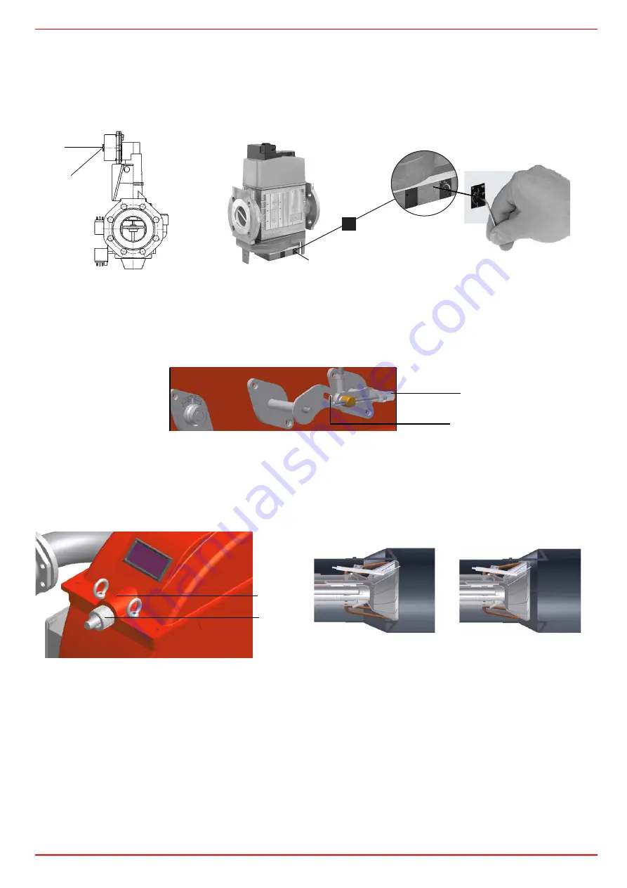
acting on the pressure stabiliser of the valves group, adjust the
gas flow rate in the high flame stage
as to meet the values
requested by the boiler/utilisation:
- Siemens VGD valves group:
remove cap
T
and act on the
VR
adjusting screw to increase or decrease the pressure and conse-
quently the gas rate; screwind
VR
the rate increases, unscrewing it decreases (see next figure).
- Dungs MBC..SE valves group:
act on its pressure governor to increase or decrease the pressure and consequently the gas
rate.
:
9
To adjust the
air flow rate in the high flame stage
, loose the
RA
nut and screw
VRA
as to get the desired air flow rate: moving
the rod
TR
towards the air damper shaft, the air damper opens and consequently the air flow rate increases, moving it far from the
shaft the air damper closes and the air flow rate decreases.
Note:
once the procedure is perfomed, be sure that the blocking nut
RA
is fasten. Do not change the position of the air damper
rods.
Note:
once the procedure is perfomed, be sure that the blocking nut
RA
is fasten. Do not change the position of the air damper
rods.
10 Only if necessary, change the combusiton head position: to let the burner operate at a lower output, loose the
VB
screw and move
progressively back the combustion head towards the MIN position, by turning clockwise the
VRT
ring nut. Fasten
VB
screw when
the adjustment is accomplished.
Attention!
if it is necessary to change the head position, repeat the air and gas adjustments described above.
11 the air and gas rate are now adjusted at the maximum power stage, go on with the point to point adjustement on the
SV1
(gas
side) adjusting cam as to reach the minimum output point.
12 as for the point-to-point regulation, move the gas low flame microswitch (cam III) a little lower than the maximum position (90°);
13 set the
TAB
thermostat to the minimum in order that the actuator moves progressively towards the low flame position;
14 move cam III to the minimum to move the actuator towards the low flame until the two bearings find the adjusting screw that refers
to the lower position: screw
V1
to increase the rate, unscrew to decrease.
15 Move again cam III towards the minimum to meet the next screw on the adjusting cam and repeat the previous step; go on this way
as to reach the desired low flame point.
16 Now adjust the pressure switches (see next paragraph).
VR
T
*OOFOTFDITLBOUTDIMàTTFM/P
"MMFOLFZOP
$MÏEFTJYQBOTNÉMFOP
$IJBWFFTBHPOBMFDBWBOS
1
#S
Siemens VGD..
Dungs MBC..SE
VRA
RA
VRT
VB
“MAX”
head position
head position
Содержание KTP1030
Страница 24: ...C I B UNIGAS M039207CB 24 HYDRAULIC DIAGRAMS Fig 16 Hydraulic diagram 3ID0023 Single burner configuration...
Страница 25: ...C I B UNIGAS M039207CB 25 Fig 17 Hydraulic diagram 3ID0014 Two or more burners configuration...
Страница 46: ...C I B UNIGAS M039207CB 46...
Страница 47: ...C I B UNIGAS M039207CB 47...
Страница 48: ...C I B UNIGAS M039207CB 48...
Страница 49: ...C I B UNIGAS M039207CB 49...
Страница 50: ...C I B UNIGAS M039207CB 50 Pumping Unit Electric Wiring Diagrams...
Страница 51: ...C I B UNIGAS M039207CB 51...
Страница 52: ...C I B UNIGAS M039207CB 52...
Страница 55: ...C I B UNIGAS M039207CB 55...
Страница 59: ......
Страница 74: ......
Страница 83: ......
Страница 84: ......
Страница 85: ...RWF50 2x RWF50 3x User manual M12922CB Rel 1 0 07 2012...
Страница 100: ...16 Note Specifications and data subject to change Errors and omissions excepted...
Страница 101: ...KM3 Modulator USER MANUAL M12927CA Rel 1 0 10 2020...
Страница 102: ...M12927CA MOUNTING 2...
Страница 118: ...1 RWF55 5X RWF55 6X User manual M12926CA Rel 0 1 10 2015...
Страница 119: ...2 DEVICE INSTALLATION Fixing system Drilling dimensions...
Страница 140: ......
Страница 141: ...23 Note Specifications and data subject to change Errors and omissions excepted...


