


CIB UNIGAS
- M039180CC
16
NOTE:
the bellow joint, the manual valve and the gaskets are not part of the standard supply.
The procedures of installation fo the gas valves are showed in the next paragraphs, according to the gas train used:
z
flanged gas trains with Multibloc Dungs MBC..SE 1900-3100-5000 or Siemens VGD40.. (flanged valves group)
Siemens VGD20.. and VGD40.. gas valves - with SKP2.. (pressure governor)
Mounting
z
When mounting the VGD.. double gas valve, two flanges are required (as for VGD20.. model, the flanges are threaded);
z
to prevent cuttings from falling inside the valve, first fit the flanges to the piping and then clean the associated parts;
z
install the valve;
z
the direction of gas flow must be in accordance with the direction of the arrow on the valve body;
z
ensure that the bolts on the flanges are properly tightened;
z
ensure that the connections with all components are tight;
z
make certain that the O-rings and gaskets between the flanges and the double gas valve are fitted.
z
Connect the reference gas pipe (
TP
in figure), to the gas pressure nipples placed on the gas pipe, downstream the gas valves: gas pres-
sure must be measured at a distance that must be at least 5 times the pipe size .
Leave the blowhole free (
SA
in figure). Should the spring fitted not permit satisfactory regulation, ask one of our service centres for a
suitable replacement.
WARNING: removing the four screws BS causes the device to be unserviceable!
MULTIBLOCDUNGS MBC1900-3100-5000SE (Flanged valves group
)
Pressure adjusting range
The pressure adjusting range, downstream the gas valves group, changes according to the spring provided with the valve group.
ATTENTION:
once the gas train is mounted according to the diagram on Fig. 6, the gas proving test mus be performed,
according to the procedure set by the laws in force.
Fig. 7
Fig. 8
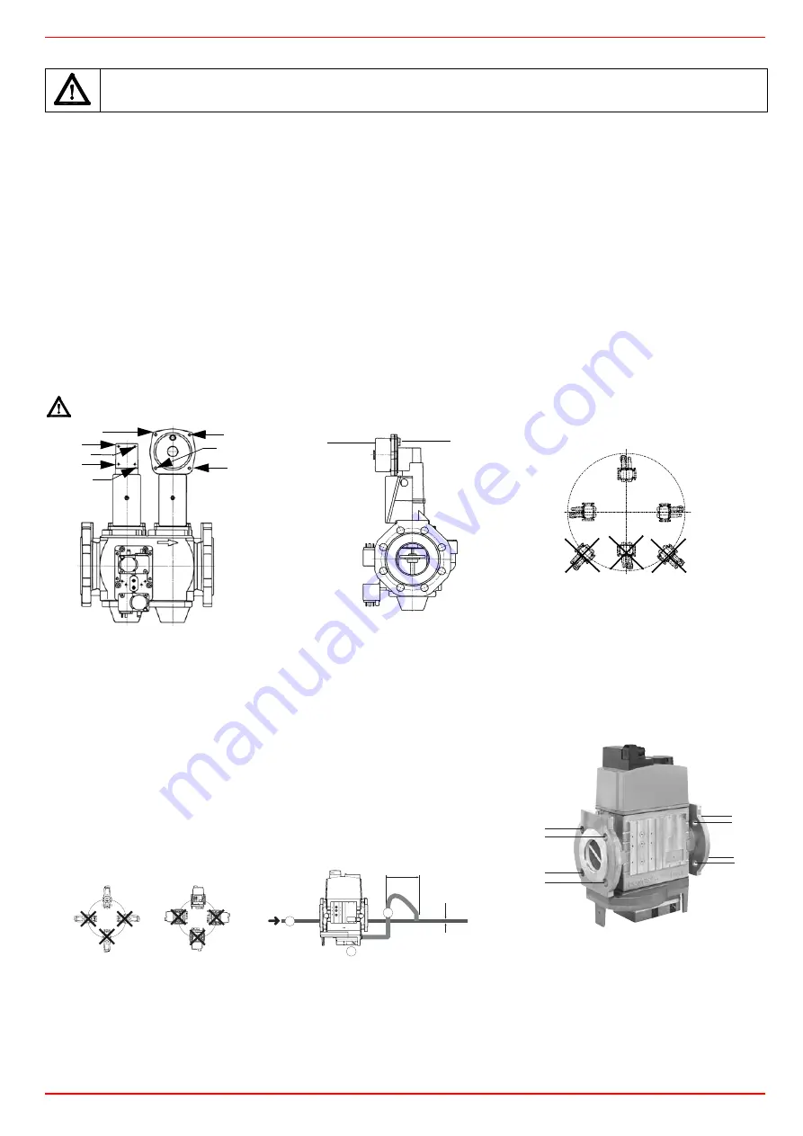
SIEMENS VGD..MOUNTING
POSITIONS
Fig. 9
Mounting
1. Insert setscrews A
2. Insert seals
3. Insert setscrews B
4. Tighten setscrews A + B.
Ensure correct seating of the seal!
6. After installation, perform leakage and functional test.
7. Disassembly in reverse order.
Fig. 10
BS
BS
SKP1.
SKP2.
BS
BS
SA
TP
7631z05/0101
Mounting positions
OPTION
10 = pulse lines
njo/!6!y!EO
EO
2
22
21
"
#
#
"
#
#
"
"


