


Alignment
of Receiver Section
1. Test Equipm ent Required
DC Pow er Supply : DC 13.8V
5.5. G.
2. Préparation fo r Alignm ent
5.5. G. : 1kHz 30% M od.(AM )
1kHz ± 1.5 kHz Dev. (FM)
Output im pédance : 8Q
Squelch : M in (Counterdockwise)
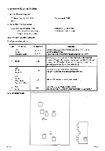
3. Alignm ent Procedure
Dummy load : 50Q
Frequency : 27.185 M H z
Attenuator : OdB = O.SpV
Step
Preset to
Adjustm ent
Remarks
1
A M
CH 19
volume : Max.
L l.2 ,3
and L11
Connect the S.S.G. to antenna jack and A F VTVM to
External speaker (J3).
Adjust coils fo r maximum reading on the A F VTVM
2
Ditto
VR4
Set the S.S.G. attenuator to -3dB and adjust the output
pow er to 5mW. (If the adjusting range is underthe desired
power, set VR2 to the minimum. If the one is over the
desired power, set it to the maximum.)
3
A M
CH 19
No MOD
VR3'
Set the S.S.G. to 1000mV output level.
Adjust VR3 so th a tth e 4 th LED just turns on.
4
A M
CH 19
Vol. : Max
Squelch : Max
VR1
Adjust VR1 so that squelch just breaks.
5
FM
CH 19
L601
Set the S.S.G. to 100pV ou tpu t level.
Adjust L601 for 4,5 + 0.2V reading on the DC Voltmeter.
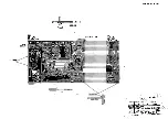
4. Alignm ent Points
U T .J 2 2 Z
H A R R Y
4
Содержание Harry
Страница 1: ...unlden SERVICE MANUAL HARRY...
Страница 11: ...un MO...
Страница 13: ...BONO LOCH O...
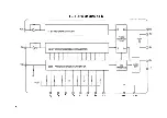
Страница 19: ...PLL BLOCK DIAGRAM IC 1 PO Pi P2 P4 p5 P7 GND VDD...
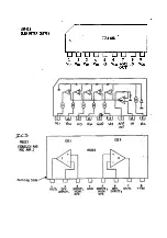
Страница 20: ...LB1423 LED METER DRIVE L B 1 4 2 3 U u u u u u u u 1 2 3 4 5 6 7 8 9 Vci Vca Vc3 V04 Q Vcs Vcc OUT...


