


Alignment of Transmitter Section
1. Test Equipm ent Required
DC Pow er Supply (DC 13.8 V)
Dummy Ioad50£2
OSC : 1 kHz
RF pow er meter
Deviation meter
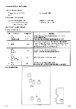
2. Alignm ent Procedure
Step
Preset to
Adjustm ent
Remarks
1
CH 19
A M
M od. 500mV
input
L6 and L9
Connect the RF pow er m eter to Antenna jack.
Adjust coils for maximum reading on the RF pow er meter.
2
No. Mod.
CH19
L6
Adjust L6(CW) fo r 4.0W reading on the RF pow er meter.
3
Ditto
VR2
Adjust VR 2 so that the 4th LED just turns on.
4
M od. 30mV
input
CH 1
FM
VR601
Adjust VR601 for ± 3kHz dev. reading on the déviation
meter.
Nöte : A fte r Alignm ent, lock w ith paraffin the area o f LS and L9.
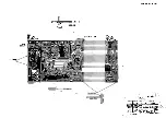
3. Alignm ent Points
и т - з « г
H A R R Y 3
Содержание Harry
Страница 1: ...unlden SERVICE MANUAL HARRY...
Страница 11: ...un MO...
Страница 13: ...BONO LOCH O...
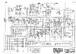
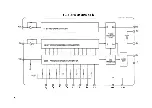
Страница 19: ...PLL BLOCK DIAGRAM IC 1 PO Pi P2 P4 p5 P7 GND VDD...
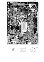
Страница 20: ...LB1423 LED METER DRIVE L B 1 4 2 3 U u u u u u u u 1 2 3 4 5 6 7 8 9 Vci Vca Vc3 V04 Q Vcs Vcc OUT...


