34
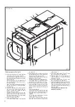
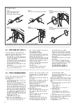
Detail 1:
Fit the brush handle extension
onto the turbulator remover
Withdraw the pin from turbulator.
Detail 2:
Fit the pin in the radial hole with a hammer.
Detail 3:
Screw the turbulator remover onto the
turbulator.
Detail 4:
Turn up to unblock the turbulator.
Detail 5:
Withdraw the turbulator
Detail 6:
Turn the remover counterclockwise to release
the turbulator
The procedure from detail 3 to 6 has to be repeated for all the turbulators.
Turbulators removal
4.2 - PRELIMINARY CHECK
Once all the hydraulic, electrical and fuel
connections have been made, before starting the
boiler we suggest to ascertain that:
- The expansion vessel and the pressure
relief valve are correctly connected and are
in no way interceptable.
- The bulb of thermometer, working, high limit
and minimum thermostats are well secured
into their proper bulb holder.
- The turbulators are correctly fitted in all the
smoke pipes.
- The C.H. circuit has been washed and rinsed
and is free from solid impurities.
- The C.H. circuit is filled with water and has
been completely purged.
- The pumps operate properly.
- The flow switch, the pressure relief valve,
and the overheating discharge valve, if any,
are adjusted at the right value.
- The fuel, hydraulic, electrical and safety
connections are executed in conformity with
national and local requirements in force.
- There are no water leaks.
- The burner has been fitted according to the
instructions of the burner
manufacturer.
- The mains voltage and frequency are
compatible with the burner and the
electrical equipment of the boiler.
- The burner is adjusted for the fuel type,
among those listed in the burner data plate,
available on the installation site, and the
burner output range is compatible with the
boiler output.
- In the boiler house there are also the burner
instructions.
- The C.H. pipes are properly insulated.
- The C.H. system is capable to absorb the
heat quantity produced at the first start of
the burner, during the test period.
-
The shunt pump is installed as
prescribed in the paragraph 2.5.6.
4.3 - FIRST COMMISSIONING
At the commissioning stage of the boiler a
qualified technician has to perform the
following checks:
- Internal and external sound test of burner
and fuel feeding pipe;
- Adjustment of the fuel throughput according
to the nominal input of the boiler (it is
convenient to remember that the nominal
input can be adjusted between the minimum
and the maximum shown in the table of
pages 6 to 10), by sharing the output between
the 1st and the 2nd stage, knowing that the
1st stage flame can go down to the 60% of
the nominal output (which at its turn can vary
between the minimum and the maximum
depending on the output
requested by the C.H. system).
Proceed, then, in the following way:
- Open the fuel feeding cock and check that
there are no leaks in the feeding line.
- Ascertain that all the switches of the
panel board are in OFF position and adjust
the working thermostat to the minimum
position.
- Switch ON the panel board through the
main switch.
- Switch ON the C.H. pump: it will start to
rotate as soon as the minimum water
temperature thermostat detects 50°C.
- Switch the burner ON.
- Position the working thermostats of 1st and
2nd stages to the maximum setting to create
a heat request.
During this phase check that:
- There are no smoke leaks from the front
door, the burner plate and the chimney
connection.
- There is a draught at the chimney base
between 2 and 4 mm w.g.
- There are no water leaks.
- The different thermostats and the other
installation safety devices work properly.
- The shunt pump operates correctly.
- The burner ignition is good.
- The burner characteristics (main
adjustments and nozzle type) correspond
to the boiler data plate.
With a burner properly adjusted it must be
possible to reach easily, from a smoke sample
taken at the chimney base, the values given
below:
1) With light oil having a maximum viscosity
of 1.5 °E at 20 °C:
- CO
2
= 12 to 13 %
- Smoke index < 1
- Smoke temperature = 190 to 210 °C
2) With Natural Gas:
- CO
2
= 9 to 10 %
- Smoke temperature = 180 to 200 °C
(values related to a clean boiler, with water
at 70 °C).
It is suggested to adjust the fuel throughput to
the actual needs of the C.H. installation (avoid
to overcharge the boiler), without
exceeding the a.m. smoke temperatures
(never go below 160 °C).
fig. 38
Содержание ELLPREX Series
Страница 1: ...26739 01 13 rev 4 ELLPREX INSTALLATION USE AND SERVICING INSTRUCTION to be kept by the user...
Страница 37: ...37 Notes...
Страница 38: ...38 Notes...
Страница 39: ...39 Notes...

