background image

Contents

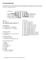
Pump Identification

 ..................................................................................................4

1.0 General

 ................................................................................................................6

1.1 Declaration of Conformity

 .................................................................................................. 6

1.2 General Description

 ............................................................................................................ 8

1.2.1 Limitation

 .................................................................................................................................................. 8

1.2.2 Noise Emission ........................................................................................................................................ 8

1.2.3 Marking - CE

 ............................................................................................................................................. 8

1.2.4 Marking - Standard

 ................................................................................................................................... 8

2.0 Before Start-Up

 ...................................................................................................9

2.1 Pump Head

 .......................................................................................................................... 9

2.2 Direction of Flow

 ................................................................................................................. 9

2.3 Pipe Layout

 ....................................................................................................................... 10

2.4 Port Positioning

 ................................................................................................................ 10

2.5 Alignment and Mounting Suggestions

 ........................................................................... 11

2.6 Clean the System Before Start-Up

 .................................................................................. 11

3.0 Shaft Seal Service

 ............................................................................................12

3.1 Double O-Lip

TM

 Seal

 .......................................................................................................... 12

3.1.1 Double O-Lip

TM

 Seal Removal

 ............................................................................................................... 12

3.1.2 Double O-Lip

TM

 Seal Installation

 ........................................................................................................... 12

3.2 Single Mechanical

TM

 Seal

 ................................................................................................. 13

3.2.1 Single Mechanical

TM

 Seal Removal

 ....................................................................................................... 13

3.2.2 Single Mechanical

TM

 Seal Installation

 ................................................................................................... 13

3.3 Seal Installation- Final Steps

 ........................................................................................... 14

4.0 Gearbox Maintenance and Service

 .................................................................15

4.1 Gearbox Disassembly

 ...................................................................................................... 15

4.2 Gearbox Assembly

 ........................................................................................................... 16

4.2.1 Assembling the Gearbox

 ....................................................................................................................... 16

4.2.2 Assembling the Gearbox- Final Steps

 .................................................................................................. 16

4.3 Lubricants and Gearbox Volumes

 ................................................................................... 17

4.4 Torque Requirements and Limits

 .................................................................................... 17

5.0 Rotor Clearances

 ..............................................................................................18

6.0 Relief Valve Cover Settings and Maintenance

 ...............................................19

6.1 Setting the Relief Valve Cover

 ......................................................................................... 20

6.1.1 Setting Relief Valve Cover: P/N 3237

 .................................................................................................... 20

6.1.2 Setting Relief Valve Cover: P/N 3239B

 ................................................................................................. 20

6.2 Relief Valve Cover Maintenance

 ...................................................................................... 21

6.2.1 Servicing Relief Valve Cover: P/N 3237

 ................................................................................................ 21

6.2.1 Servicing Relief Valve Cover: P/N 3239B

 ............................................................................................. 21

7.0 Troubleshooting

 ...............................................................................................24

8.0 Pump Dimensions ............................................................................................26

9.0 Parts Lists

 .........................................................................................................30

Содержание UNIBLOC-PD 501

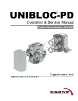
Страница 1: ...Operation Service Manual UNIBLOC PD UNIBLOC PUMP Tanker Pump Models 501 576 Original Instructions MANUAL NO PD501 576 REVISION 01 2017 ...

Страница 2: ... recording for any purpose without the express written permission of Unibloc Pump Inc Copyright 2017 Unibloc Pump Inc All Rights Reserved Revision Date 01 2017 Manual No PD501 576 UNIBLOC PUMP Unibloc Pump Inc 1701 Ashborough Road SE Marietta Georgia 30067 USA Tel 770 218 8900 Fax 770 218 8442 E Mail info uniblocpump com www uniblocpump com Unibloc Pump AB Lantvärnsgatan 4 652 21 Karlstad Sweden T...

Страница 3: ...echanicalTM Seal Removal 13 3 2 2 Single MechanicalTM Seal Installation 13 3 3 Seal Installation Final Steps 14 4 0 Gearbox Maintenance and Service 15 4 1 Gearbox Disassembly 15 4 2 Gearbox Assembly 16 4 2 1 Assembling the Gearbox 16 4 2 2 Assembling the Gearbox Final Steps 16 4 3 Lubricants and Gearbox Volumes 17 4 4 Torque Requirements and Limits 17 5 0 Rotor Clearances 18 6 0 Relief Valve Cover...

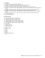
Страница 4: ...standard cover 15 standard housing with cooling heating jacket 20 vented cover D Rotor Housing Type 10 standard sanitary housing 15 standard cover with cooling heating jacket E Connection Type Size P Clamp L ACME thread K NPT male D DIN threads AF 150 ANSI flange DF DIN flange 25 2 5 inch 30 3 0 inch 40 4 0 inch H horizontal port configuration V vertical port configuration F Rotor Type 61 Class D ...

Страница 5: ... for metallic rotor and for Danfoss hydraulic motor 31 standard 316L stainless steel drive shaft with hardened seal area for metallic rotor and for Danfoss hydraulic motor 32 standard 316L stainless steel drive shaft with sleeve for metallic rotor and for Danfoss hydraulic motor T top mounted drive shaft B bottom mounted drive shaft H Shaft Seal Type 10 single mechanical carbon vs stainless steel ...

Страница 6: ...h in EC Directive 2006 42 EC If the product is modified without our written permission or if the safety instructions in the instruction manuals are not being followed this declaration becomes invalid Machine Description Rotary Lobe Pump Product Denomination UNIBLOC PD Model Type PD200 677 Standards Applicable Harmonized Standards o EN 809 A1 2009 Pumps and Pump Units for Liquids Common Safety Requ...

Страница 7: ...ion manuals are not being followed this declaration becomes invalid Machine Description Rotary Lobe Pump Assembly Product Denomination UNIBLOC PD GP ASSEMBLY Model Type PD200 677 GP200 450 Directives Applicable Directives o Electromagnetic Compatibility Directive 2004 108EC o Low Voltage Directive 2006 95 EC Standards Applicable Harmonized Standards o EN 809 A1 2009 Pumps and Pump Units for Liquid...

Страница 8: ... and or serial number when asking for assistance 1 2 4 Marking Standard Standard marking is machined on the side of pumps bearing housing See figure 1 4 for details Pump size is machined on rotor housing next to the ports Figure 1 4 1 2 General Description UNIBLOC PD is a positive displacement rotary lobe pump It may be supplied with a drive unit figure 1 0 or without a drive unit figure 1 1 When ...

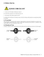
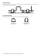
Страница 9: ...d grinding 2 1 Pump Head Remove the front cover and make sure that no particles are trapped inside the rotor housing Check that the rotor bolts have been securely tightened if design provides such an option If possible make sure pump turns freely Put back cover making sure o ring remains in place and securely tighten the four front cover nuts 2 2 Direction of Flow The pump is designed to operate i...

Страница 10: ...IGHT 2 3 Pipe Layout When connecting pipes to the pump make sure they are well supported as the pump is not meant to serve this purpose Keep in mind that pipes filled with liquid are very heavy 2 4 Port Positioning UNIBLOC PD is designed to accommodate both vertical and horizontal product through puts ...

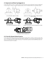
Страница 11: ... WITH VERTICAL PORTS FLOW FLOW PTO PUMP WITH HORIZONTAL PORTS FLOW FLOW HYDRAULIC DRIVE PUMP WITH HORIZONTAL PORTS STATIONARY UNIT ON BASEPLATE 2 6 Clean the System Before Start Up Clean system of all debris before start up Any remaining particles larger than 0 002 in 0 05 mm can damage the pump if they enter it A filtering device installed before the pump inlet is highly recommended to insure saf...

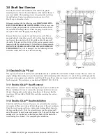
Страница 12: ... Double O LipTM Seal This type of seal is most frequently used with liquids that are very difficult to seal because of high viscosity The seal comes as a single cartridge that is easily serviced The maximum shaft rotational speed for this seal is 1 5 m s 4 8 ft s or 500 rpm and the maximum service pressure should not exceed 10 bar 150 psig The seal does not require external lubrication and can be ...

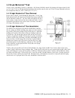
Страница 13: ... of the rotor housing to show pin hole locations Take the stationary portion of the seal face kit 92 and lubricate o ring already installed Note location of pin slots on stationary portion of seal face and on stationary seal holder Ink markings can be made on surface of rotor housing to show location of pins and similar markings can be made on seal face to show location of pin slots Align pin slot...

Страница 14: ...gs seat properly The rotors must make contact with the shafts Place o rings 26 on the rotor bolts 14a 14b Lubricate them and the rotor bores Place a nonmetal object between the rotors to keep them from turning Thread the rotor bolts into the shaft ends Turn the drive shaft to make sure the rotors turn freely Measure the clearances between the rotor housing and the rotors Compare these values with ...

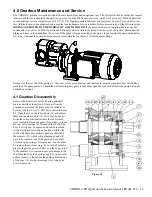
Страница 15: ...als must be completed first before disas sembly of the pump gearbox The method of removing these parts is dependent upon the type of shaft seals the pump has and is outlined in section 3 4 1 Gearbox Disassembly Remove the front cover rotors housing and shaft seals as described in section 2 Drain oil from the gearbox by removing the drain plug if available or by removing the cover 7 PTO drive shown...

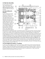
Страница 16: ...4a 14b in the splined shaft ends with the rotors on Do not set the tabs on the tab washers Remove the rotor bolts and rotors Push the ro tor housing 1 onto the dowels 20 in the gearbox and tap gently with a rubber mallet to seat it properly Insert the housing studs 15 and secure them with the split washers 44 and hex nuts 43 Slide the rotors 3a 3b on to the corresponding shaft One rotor and one sh...

Страница 17: ...evel check plug If oil does not come out of this hole it must be added through the vent hole until it starts to do so Reattach the vent and oil plug and resume operation 4 4 Torque Requirements and Limits MANUFACTURER LUBRICANT NAME TEMP RANGE C F Mobil SHC 627 SHC 634 23 121 10 250 121 152 250 305 Exxon Spartan EP 100 Spartan EP 150 23 121 10 250 121 152 250 305 Shell Spirax S 75W90 23 152 10 305...

Страница 18: ...MODEL POSITION 1 6 7 8 10 9 11 501 26 28 10 2 11 0 38 40 15 0 15 7 20 22 7 9 8 7 10 12 3 9 4 7 551 27 33 10 6 13 0 36 42 14 2 16 5 21 24 8 3 9 4 12 15 4 7 5 9 576 30 32 11 8 12 6 31 33 12 2 13 0 20 22 7 9 8 7 10 12 3 9 4 7 CLEARANCES FOR CLASS E STAINLESS STEEL ROTORS x0 01 mm x0 001in UNIBLOC MODEL POSITION 1 6 7 8 10 9 11 501 32 34 12 6 13 4 38 40 15 0 15 7 24 26 9 4 10 2 13 15 5 1 5 9 551 34 40...

Страница 19: ...he pump is always at the inlet of the relief valve No 3239B functions in both directions The pressure is set in conjunction with a pressure gauge installed on the discharge side of the pump By compressing or decompressing the spring inside the valve the pressure at which the valve will open can be adjusted This must be done while the pump is operating at the desired flow rate Extreme cau tion shou...

Страница 20: ...ly 0 3 0 7 bar 5 10 psig lower than the desired relief pressure since the pump will continue to build pressure even though the valve may be open Return the housing 10 and tighten 6 1 2 Setting Relief Valve Cover P N 3239B Release the lock ring 8 and turn it and the adjusting sleeve spring adjuster 7 clockwise until they bottom out Turn the sleeve adjuster counterclockwise until the pressure gauge ...

Страница 21: ...e the housing 10 and tighten The pump may now be returned to service 6 2 1 Servicing Relief Valve Cover P N 3239B Mark the location of the lock ring 8 on the spring adjuster 7 Unscrew the spring adjuster 7 and remove it Remove the spring 9 Look for the diaphragm washer 5 either inside the adjuster or on top of the spring for replacement Unscrew the dome nuts on the spring housing 6 and separate th...

Страница 22: ...IDEAS INCORPORATED IN ITS DESIGN IS THE EXCLUSIVE PROPERTY OF UNIBLOC PUMP INC ITS ACCEPTANCE CONSTITUTES AN AGREEMENT THAT IT SHALL BE TREATED AS A CONFIDENTIAL DOCUMENT USED FOR NO OTHER PURPOSE THAN TO AID IN ITS CONSTRUCTION THAT IT IS TO BE RETURNED UPON REQUEST AND THAT IT IS NOT TO BE DISCLOSED OR COPIED EXCEPT AS AUTHORIZED IN WRITING BY UNIBLOC PUMP INC UNIBLOC PUMP 0 ...

Страница 23: ...TLE RELIEF VALVE ASSEMBLY JUN 11 2014 ALL DIMENSIONS IN MM DRAWN CHECKED APP D SCALE DATE BY KL NO SCALE 06 11 14 THIS DRAWING AND ALL IDEAS INCORPORATED IN ITS DESIGN IS THE EXCLUSIVE PROPERTY OF UNIBLOC PUMP INC ITS ACCEPTANCE CONSTITUTES AN AGREEMENT THAT IT SHALL BE TREATED AS A CONFIDENTIAL DOCUMENT USED FOR NO OTHER PURPOSE THAN TO AID IN ITS CONSTRUCTION THAT IT IS TO BE RETURNED UPON REQUE...

Страница 24: ...SHA too low 2 Pump runs too slow 3 Increased slip in pump 4 Discharge pressure higher than expected 4 Front cover not tight 1 See A 3 2 Increase speed Check hydraulic pressure and filter 3 Check rotor clearances replace worn parts if necessary 4 Check discharge piping for closed valves or obstructions Increase pump speed BUT DO NOT EXCEED PRESSURE LIMITS OF PUMP Increase discharge pipe size Increa...

Страница 25: ...oo high 1 See C 2 Check pump shaft seals for leaks Check suction side pipe fittings for leaks Increase NPSHA 3 Check suction and discharge piping for closed valves or obstructions Increase pump size F Motor overheating 1 Motor size too small 2 Discharge pressure too high 3 Viscosity higher than expected 4 Motor pump misalignment 1 Increase motor size 2 Lower pump speed Lower pressure Check suction...

Страница 26: ...26 UNIBLOC PD Operation Service Manual PD501 576 8 0 Pump Dimensions UNIBLOC PUMP ...

Страница 27: ...UNIBLOC PD Operation Service Manual PD501 576 27 UNIBLOC PUMP ...

Страница 28: ...28 UNIBLOC PD Operation Service Manual PD501 576 UNIBLOC PUMP ...

Страница 29: ... ALL IDEAS INCORPORATED IN ITS DESIGN IS THE EXCLUSIVE PROPERTY OF UNIBLOC PUMP INC ITS ACCEPTANCE CONSTITUTES AN AGREEMENT THAT IT SHALL BE TREATED AS A CONFIDENTIAL DOCUMENT USED FOR NO OTHER PURPOSE THAN TO AID IN ITS CONSTRUCTION THAT IT IS TO BE RETURNED UPON REQUEST AND THAT IT IS NOT TO BE DISCLOSED OR COPIED EXCEPT AS AUTHORIZED IN WRITING BY UNIBLOC PUMP INC UNIBLOC PUMP 0 ...

Страница 30: ...30 UNIBLOC PD Operation Service Manual PD501 576 UNIBLOC PUMP 9 0 Parts Lists ...

Страница 31: ...UNIBLOC PD Operation Service Manual PD501 576 31 UNIBLOC PUMP ...

Страница 32: ...EIGHT RELEASE DATE DWG NO DWG TITLE FLANGE MOUNT ASSEMBLY AUG 30 2013 ALL DIMENSIONS IN MM DRAWN CHECKED SCALE DATE BY KL 1 5 08 30 13 THIS DRAWING AND ALL IDEAS INCORPORATED IN ITS DESIGN IS THE EXCLUSIVE PROPERTY OF UNIBLOC PUMP INC ITS ACCEPTANCE CONSTITUTES AN AGREEMENT THAT IT SHALL BE TREATED AS A CONFIDENTIAL DOCUMENT USED FOR NO OTHER PURPOSE THAN TO AID IN ITS CONSTRUCTION THAT IT IS TO B...

Страница 33: ...UNIBLOC PD Operation Service Manual PD501 576 33 3 ...

Страница 34: ......

Страница 35: ......

Страница 36: ...on inspection of the item in question poor workmanship or defective materials are revealed Unibloc Pump will repair or replace it at Unibloc Pump s option and will return it by shipping it F O B the service facility This warranty is void if the item has not been used as recommended or instructed has been altered or used with unauthorized accessories has been subject to misuse abuse or accident or ...

Отзывы: