


11
5.
4B
OPERATING PROCEDURE
5.1.
22B
Cautions in Operation
(1)
When power is applied to this instrument, measurement starts about three seconds later. However,
start measurement more than 30 minutes after turning power ON until the indicated value is
stabilized because there can be temperature drift or other problem for some time after power is
turned ON.
If the sensor head is used to measure low pressure (for example, CMMT-10A) or if an effective
digit below 1/1000 of the full scale of the sensor head is required, start measurement after applying
power continuously for more than 2 hours until temperature equilibrium of the sensor head is
attained.
Do not turn the power OFF when a series of measurements is being made.
(2)
This controller uses an absolute pressure type vacuum gauge of which measurement value is not
affected by the type of gas, but its characteristics may change if the sensor head is exposed to a
chemically active gas or a gas with high adsorptivity.
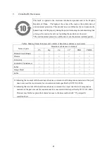
(3)
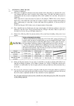
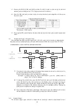
Refer to the following table, the proof pressure of the sensor head, including when power is not
applied.
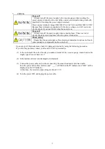
Usage environment precautions
Do not connect the sensor outside the VCO, VCR, UFC joint specification in a
location where the sensor's internal pressure exceeds atmospheric pressure. If the
sensor's internal pressure exceeds atmospheric pressure, it may pose a hazard to
its surroundings, including to people, if the gauge head flies off its connector.
There is also a risk of malfunction or damage to the sensor if the sensor interior
exceeds the maximum usable pressure. Where there is a risk of exceeding the
maximum usable pressure, ensure that the sensor interior will not exceed the
maximum usable pressure with a gate valve.
Model
CCMT-1000A
CCMT-100A
CCMT-10A
Maximum usable
pressure
160 kPa (abs)
Atmospheric
pressure
Atmospheric
pressure
Model
CCMT-1000D
CCMT-100D
CCMT-10D
CCMT-1D
Maximum usable
pressure
400 kPa (abs)
260 kPa (abs)
260 kPa (abs)
260 kPa (abs)
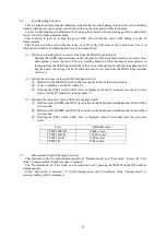
(4)
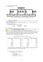
Before starting measurement, it is necessary to correct the zero point at a pressure sufficiently lower
than the measurement pressure. If the ultimate pressure of a system to which the sensor head is
attached is not sufficiently low for zero point correction, the specifications of this instrument may
not be met.
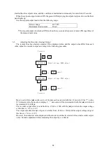
(5)
The zero point correction is made by using the 0 ADJ function of the sensor head in conjunction
with the zero point correcting function of this controller. The zero adjusting function of the sensor
head is for coarse adjustment and that of this controller is for fine adjustment.
The zero point correcting function of this controller is reset by turning the power OFF. So keep this
in mind during operation.
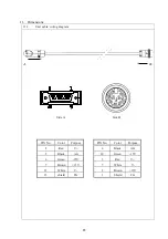
Содержание GM-2001
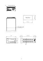
Страница 9: ...3 1 4 Dimensional drawing Panel Cut Control unit...
Страница 12: ...6 Fig 2 2 Rear panel...
Страница 28: ...22 10 9BCertificate of Contamination...


