Ulvac GM-2001 Скачать руководство пользователя страница 1

No. SK00-7107-EI-003-03 


CAPACITANCE MANOMETER 

CONTROLLER 


MODEL GM-2001/2002 


Instruction Manual 


Components Division, 

ULVAC, Inc. 


http://www.ulvac.co.jp/


This manual is for units of the following serial 
numbers: 

S/N:00001 and higher.


Read this manual before operation and keep it at 
hand for immediate reference.


Содержание GM-2001

Страница 1: ...ROLLER MODEL GM 2001 2002 Instruction Manual Components Division ULVAC Inc http www ulvac co jp This manual is for units of the following serial numbers S N 00001 and higher Read this manual before op...

Страница 2: ...ety Symbols Safety symbols are used throughout this instruction manual to call the operator s attention to safety The terminology used in safety symbols is classified below Indicate status of urgency...

Страница 3: ...CO VCR UFC joint specification in a location where the sensor s internal pressure exceeds atmospheric pressure If the sensor s internal pressure exceeds atmospheric pressure it may pose a hazard to it...

Страница 4: ...h the wiring before turning the power on There is a risk of damage and fire if wired incorrectly Check power supply voltage Before turning on the power supply check that the vacuum gauge operating vol...

Страница 5: ...culation formula added to recorder output Nov 1 2013 02 Quick manual added Optional power cable added Warranty changes Added pollution certificate Dec 6 2019 03 Added product phot to cover Added Revis...

Страница 6: ...F CONTOLLER 12 6 1 GENEAL FLOWCHART 12 6 2 SELECTION THE RECORDER OUTPUT 12 6 2 1 Recorder Output 12 6 3 SETTING THE UNIT OF PRESSURE AND POSITION OF DECIMAL POINTPUT 14 6 4 DISPLAY AND CHANGE OF SETP...

Страница 7: ...decimal point Accuracy Refer to display range change function High pressure 100 FS 10 FS 0 20 FS 1digit 0 005 fs Low Pressure 12 5 FS 0 32 FS 1digit 0 005 fs Example CCMT 10A High pressure 1333 2PaFS...

Страница 8: ...depending on the type 1 Controller GM 200 1 pc 2 Quick manual 1 pc 1 3 Option 1 Sensor head CCMT 1000A D 133 32 kPa F S CCMT 100A D 13 332 kPa F S CCMT 10A D 1333 2 Pa F S CCMT 1D 133 32 Pa F S 2 Sens...

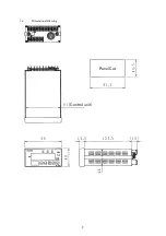
Страница 9: ...3 1 4 Dimensional drawing Panel Cut Control unit...

Страница 10: ...put adjustment set value in addition to the current measurement value If the measurement value exceeds the scale or the sensor head is not connected ____ will be displayed by blinking On the CCMT D Se...

Страница 11: ...and do not short the fuse holder There is a risk of damage and fire Check wiring Ensure that the power supply cable crimping terminal section does not touch other conductive components on the control...

Страница 12: ...6 Fig 2 2 Rear panel...

Страница 13: ...iring Ensure that the power supply cable crimping terminal section does not touch other conductive components on the control etc Upon receipt of this instrument check if it damaged in transit by using...

Страница 14: ...0D CCMT 10D CCMT 1D Maximum usable pressure 400 kPa abs 260 kPa abs 260 kPa abs 260 kPa abs Operating conditions warning Use the vacuum gauge and capacitance manometer in an environment within the ran...

Страница 15: ...a cause of error when a low pressure is measured 4 Avoid installation in a high temperature high humidity place 4 3 19BInstalling the controller 1 Mounting panel a This instrument is the panel mounti...

Страница 16: ...er supply cable crimping terminal section does not touch other conductive components on the control etc Check wiring For safety always connect the GND terminal to a ground Check power supply voltage B...

Страница 17: ...xceeds atmospheric pressure If the sensor s internal pressure exceeds atmospheric pressure it may pose a hazard to its surroundings including to people if the gauge head flies off its connector There...

Страница 18: ...een the recorder output voltage and the indicated measured value changes the recorder output can be adjusted using the output voltage adjusting function The adjusting procedure will be described later...

Страница 19: ...1D 1 Lin1 output graph Example CCMT 10A 2 Lin2 output graph Example CCMT 10A 0 100 200 300 400 500 600 700 800 900 1000 1100 1200 1300 1400 0 1 2 3 4 5 6 7 8 9 10 11 12 13 Pressure Pa Output V 0 10 2...

Страница 20: ...1 10 of the full scale value of the sensor head the position of the decimal point is automatically shifted by one digit to enhance the resolution of the measurement value Set the unit of pressure and...

Страница 21: ...t mode can be switched over by pressing the ALM switch on the front panel Select a desired indicator while watching the SV indicator Example To display change the value of SETPOINT 1 press the ALM swi...

Страница 22: ...e recorder output according to the following procedure Data is set with the switch and of the data can be selected with the switch If the on the SV indicator in the figure above displays _ data value...

Страница 23: ...invalid and a zero reset value from the ZERO input terminal will be set 2 Setting the zero reset value with the front panel switch Hold down the ZERO switch on the front panel for more than two second...

Страница 24: ...ot Change when Pressure is Changing Possible cause Corrective action 1 The measurement mode is not selected Example The setpoint value is displayed 1 Select the measurement mode If the measurement mod...

Страница 25: ...lace the sensor head 3 There is a leak in the neighborhood of the sensor head or area where the sensor head is attached 3 Leak in the sensor head Replace it Leak in other area Stop the leak 4 Poor con...

Страница 26: ...local ULVAC representatives for repair Return charge shall be paid by Buyer Disclaimer 1 Failure occurred after expiration of warranty period 2 Failure caused by force majeure such as fire storm and...

Страница 27: ...at for names and contents of hazardous substances or elements Name of parts Hazardous substances or elements Pb Hg Cd Cr6 PBB PBDE Printed Circuit Board Chassis Connector Controller Transformer Label...

Страница 28: ...22 10 9BCertificate of Contamination...

Страница 29: ...1 1 35BUnit cable wiring diagram Side A Side B PIN No Color Purpose PIN No Color Purpose 5 Red V 6 Black AG 5 Black AG 10 Green 15V 6 Green 15V 1 Red V 7 Brown 15V 7 White V 12 White V 2 Brown 15V 15...

Отзывы: