background image

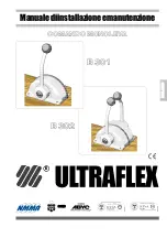
SINGLE LEVER CONTROL B301 AND B302


-  

page 5 

of 47

Installation and maintenance  manual

ULTRAFLEX

E

N

G

L

ISH

WARRANTY

ULTRAFLEX 

 warrants that its products are built according to the standards of good workmanship and are free

of  defects  in  materials  and  workmanship.

This warranty is valid for two years starting on the date of manufacture with the exception of cases in which

products  are  installed  and  used  on  working  vessels  or  on  vessels  commercial  use,  in  which  case  the

guarantee  is  limited  to  1  year  from  the  date  of  manufacture.

This  warranty  is  limited  to  free  replacement  or  repair  of  the  item,  which  must  be  returned  carriage  paid,

provided  we  find  it  to  be  effectively  defective  in  materials  and/or  workmanship.

The  warranty  does  not  cover  any  direct  or  indirect  damages,  The  warranty  specifically  does  not  cover,  and

we shall not be liable for (except for replacement or repair of defective items under the terms and conditions

set forth above), malfunctioning of our products if their failure or poor functioning is attributable to incorrect

installation  or  to  negligent  or  improper  use.

This  warranty  does  not  cover  products  installed  on  racing  boats  or  used  in  a  competitive  context.  The

descriptions  and  illustrations  in  this  manual  are  indicative  only.

Please  contact  our  Assistance  Service  for  more  detailed  information.

The components of 

ULTRAFLEX 

steering and control systems with EC marked components. (See Art. 3 and Art.

5  of  directive  94/25/EC.)  Note  that  the 

ULTRAFLEX

  warranty  shall  be  automatically  forfeited  if  any 

ULTRAFLEX

components  are  installed  in  a  steering  and  control  system  along  with  products  of  other  brands.

INTRODUCTION

This  installation  and  maintenance  manual  constitutes  an  integral  part  of  the  product  and  must  be  made

easily  accessible  for  personnel  using  the  product  and  performing  maintenance  work  on  it.

The  user  must  know  the  content  of  this  manual.

ULTRAFLEX

 shall not be held liable for any inaccuracies due to printing errors in the manual.

Without altering the basic features of the product described 

ULTRAFLEX 

reserves the right to make any changes to

descriptions, details and illustrations that it may consider appropriate for its improvement or for manufacturing

or commercial reasons at any time, without being required to update this publication immediately.

ALL RIGHTS RESERVED. Rights to publication, trademarks, logos and photographs of 

ULTRAFLEX

 products present

in this manual are the property of 

ULTRAFLEX

and may not be reproduced in full or in part. Great care has been

taken to collect and verify documentation to make this manual as complete and easy to understand as possible.

None of the information obtained in this publication may be interpreted as a guarantee or an express or implicit

condition- including but not limited to, the guarantee of suitability for a particular purpose. None of  the information

contained  in  this  publication  may  be  interpreted  as  a change  to or  assertion  of  the  terms  of any  contract  of

purchase.

The product must be installed by experienced personnel to ensure correct functioning of the product and its

components.  In  the  event  of  breakage  of  the  components  or  malfunctioning,  contact  specialized  personnel

or  our  Technical  Assistance  Service.

WARNING

TECHNICAL ASSISTANCE SERVICE

UFLEX  S.r.l.

Via  Milite  Ignoto,8A

16012  Busalla  (GE)-Italia

Tel:  +39.010.962.01

Fax:  +39.010.962.0333

Email:  [email protected]

www.ultraflexgroup.it

North  -  South  -  Central  America:

UFLEX

 USA

6442  Parkland  Drive

Sarasota,  FL  34243

Tel:  +1.941.351.2628

Fax:  +1.941.360.9171

Email:  [email protected]

www.uflexusa.com

Содержание B 301

Страница 1: ...SINGLE LEVER CONTROL Installationandmaintenancemanual PARTNER R B 301 B 302 ENGLISH Dr No 23166 d 01 10 2017 I UK F page 2 pag 17 page 33 ITA LIANO F R A N A IS...

Страница 2: ...cesses starting from the design in order to ensure product quality to the customer maintain and improve the quality standards constantly pursue a continuous process improvement to meet the market need...

Страница 3: ...ON 8 3 3 ADJUSTMENT OF THE LEVER INCLINATION 8 3 4 CONNECTING CONTROL CABLE 9 3 5 INSTALLATION OF CABLES C14 AND MACH 14 9 3 5 1 SHIFT CABLE CONNECTION 9 3 5 2 THROTTLE CABLE CONNECTION 11 3 6 ADJUSTI...

Страница 4: ...lains the meaning of some nautical words contained in this manual DANGER Immediate hazards which CAUSE severe personal injury or death WARNING CAUTION Operations which should be performed by qualified...

Страница 5: ...constitutes an integral part of the product and must be made easily accessible for personnel using the product and performing maintenance work on it The user must know the content of this manual ULTRA...

Страница 6: ...cables except the C4 K59 kit is included with both the controls necessary to install Ultraflex C2 C8 C0 and Mach 0 cables For all the other cables the following kits are available on demand K 60 for...

Страница 7: ...check that all the components supplied with it are contained in the package refer to list If you identify any damage notify the carrier and your supplier WARNING Personnel handling the load must work...

Страница 8: ...ith a 17 socket wrench 3 3 2Controlboxinstallation 1 Install the control in a position that allows the lever to rotate free and take care that it can reach the full forward and full reverse stroke 2 R...

Страница 9: ...r each cable type K59 kit is also included with both single levers B301 and B302 To install the cables on the control controls follow the instructions provided with each kit To install the cables C14...

Страница 10: ...ear See the possible strokes on the control device and select the nearest one for instance if the stroke on the engine from one end of stroke to the other is 67 mm the cable must be connected to the m...

Страница 11: ...erwise check that the control shift stroke corresponds to the engine one 13 I G H 14 3 5 2 Throttle cable connection 1 Remove the cable fastener 7 from the plate 8 removing the screws 9 3 Engage the r...

Страница 12: ...ment To check the friction of the lever move it clockwise and counter clockwise ADJUSTING THE CLUTCH MUST BE PERFORMED WITH ENGINE TURNED OFF AND THE LEVER IN THROTTLE POSITION 3 CONTROL B301 Place th...

Страница 13: ...ing unexepected movements of the boat To assemble it do as follows 2 Position the device 23 on plate 22 inserting the cylinder 24 inside the plastic guide 25 19 20 23 24 22 25 21 If you are installing...

Страница 14: ...iteria indicated below ULTRAFLEX shall not be held liable for the user s failure to observe these precautions and criteria and shall not be held liable for any negligence in use of the system NEVER PU...

Страница 15: ...tighten if necessary WARNING DANGER Loosening or separation of nuts holding the system in place can cause not only malfunctioning of the single lever control but damage or injury Periodically check th...

Страница 16: ...Installationandmaintenancemanual ULTRAFLEX page16of47 SINGLE LEVER CONTROL B301 AND B302 ENGLISH NOTES...

Страница 17: ...COMANDO MONOLEVA Manualediinstallazioneemanutenzione SOCIO R B 301 B 302 ITA LIANO...

Страница 18: ...tempo gli standard di qualit perseguire un continuo miglioramento dell efficacia e dell efficienza dei processi per poter essere sempre in sintonia con le esigenze del mercato ed accrescere la soddisf...

Страница 19: ...DEI CAVI DI CONTROLLO 25 3 5 INSTALLAZIONE CAVI C14 E MACH 14 25 3 5 1 COLLEGAMENTO DEL CAVO PER IL CONTROLLO DELL INVERTITORE 25 3 5 2 COLLEGAMENTO DEL CAVO PER IL CONTROLLO DEL GAS 27 3 6 REGOLAZION...

Страница 20: ...ci contenuti nel presente manuale PERICOLO Danni immediati che CAUSANO ferite gravi alla persona o che portano alla morte AVVERTENZA ATTENZIONE Le operazioni per la cui esecuzione si richiede onde evi...

Страница 21: ...allazione e manutenzione costituisce parte integrante del prodotto e deve essere facilmente reperibile dal personale addetto all uso e alla manutenzione dello stesso L utilizzatore tenuto a conoscere...

Страница 22: ...mando possono utilizzare tutti i cavi Ultraflex per il comando motore ad eccezione di C4 in dotazione con entrambi i modelli viene incluso il kit K59 necessario per il collega mento dei cavi Ultraflex...

Страница 23: ...di serie siano contenuti nell imballo vedi elenco In caso di danneggiamento notificare il reclamo allo spe dizioniere ed avvisare il vostro fornitore AVVERTENZA Il personale addetto alla manipolazione...

Страница 24: ...e a tubo da 17 3 3 2Posizionamentodellascatoladicomando 1 Posizionare la scatola di comando in modo da consentire la rotazione completa della leva dalla posizione marcia avanti alla posizione marcia i...

Страница 25: ...a avere pieno accesso agli ele menti su cui an dranno fissati i cavi 4 5 5 COMANDO B302 Separare le due scatole 6 rimuo vendo le viti 5 5 5 6 6 3 Per ciascun modello di cavo previsto un kit di accesso...

Страница 26: ...a avanti a marcia indietro Riferirsi alle corse disponibili sul meccanismo di comando e scegliere quella che piu si avvicina per esempio se la corsa rilevata sul motore da finecorsa a finecorsa risult...

Страница 27: ...do ed invertitore sul motore 13 I G H 14 3 5 2 Collegamento del cavo per il controllo del gas 1 Rimuovere il fermaguaina 7 alla piastra 8 svitando le viti 9 3 Innestare il puntale 16 sul perno 17 7 8...

Страница 28: ...ificare il grado di frizionamento della leva muovere la stessa alternativamente in direzione oraria e antioraria LA REGOLAZIONE DELLE FRIZIONE DEVE ESSERE ESEGUITA A MOTORE SPENTO PORTANDO LA LEVA IN...

Страница 29: ...evitando movimenti pericolosi dell imbarcazione Per il montaggio procedere come segue 2 Posizionare il di spositivo 23 sulla pia stra 22 inserendo il cilindretto 24 all inter no dell apposita guida i...

Страница 30: ...i seguito ULTRAFLEX declina ogni responsabilit nel caso in cui l utilizzatore non li osservi cos come non respon sabile per qualsiasi tipo di negligenza che venga commessa durante l utilizzo del siste...

Страница 31: ...L allentamento o la separazione dei dadi di fissaggio pu causare oltre al malfunzionamento del sistema di guida danni a persone e a cose Periodicamente controllare che non vi sia corrosione sulle par...

Страница 32: ...Manuale di installazione e manutenzione ULTRAFLEX pag 32di47 COMANDO MONOLEVA B301 E B302 ITA LIANO NOTE...

Страница 33: ...COMMANDE MONO LEVIER Manueld installationetd entretien ASSOCIE R B 301 B 302 F R A N A IS...

Страница 34: ...s d entreprise partir de la conception du projet au but de assurer au client la qualit du produit maintenir et am liorer continuellement les standard de qualit poursuivre une am lioration continue de...

Страница 35: ...NT DES CABLES DE CONTROLE 41 3 5 INSTALLATION CABLES C14 ET MACH 14 41 3 5 1 CONNEXION DU CABLE POUR LE CONTROLE DE L INVERSEUR 41 3 5 2 CONNEXION DU CABLE POUR LE CONTROLE DU GAZ 42 3 6 REGLAGE DU DI...

Страница 36: ...autiques contenus dans ce manuel DANGER Dommages imm diats qui CAUSENT des blessures graves la personne ou bien qui en provoquent la mort AVERTISSEMENT ATTENTION Les op rations pour l ex cution desque...

Страница 37: ...entretien est une partie int grante du produit et il doit tre facilement rep rable par le personnel pr pos son emploi et son entretien L usager doit conna tre le contenu de ce manuel La Soci t ULTRAFL...

Страница 38: ...exception du C4 le kit K59 n cessaire pour la connexion des c bles Ultraflex C2 C8 C0 Mach 0 est fourni avec les deux mod les Pour les autres c bles les kits suivants sont pr vus sur demande K 60 pour...

Страница 39: ...de l quipement standard soient dans l emballage voir liste En cas d endommagement notifier la r clamation au transporteur et informer votre fournisseur AVERTISSEMENT Le personnel charg de la manipulat...

Страница 40: ...ment la vis t te hexagonale 3 l aide d une cl au moyen d une cl tube de 17 3 3 2Positionnementdelamanette 1 Positionner la manette de sorte permettre la rotation compl te du levier de la position marc...

Страница 41: ...sorte atteindre librement les l ments o les c bles seront fix s 4 5 5 C O M M A N D E B302 S parer les deux manettes 6 en enlevant les vis 5 5 5 6 6 3 Un kit d accessoires est pr vu pour chaque mod le...

Страница 42: ...nt rieur tourn vers le haut Ins rer le pivot I dans un des trous a b ou c pr sents sur le balancier inverseur de la manette 12 NOTE Le trou est choisi en fonction de la course qu on veut faire effectu...

Страница 43: ...ondance de la course entre manette et inverseur sur le moteur 13 I G H 14 3 5 2 Connexion du c ble pour le contr le du gaz 1 Enlever la but e de gaine 7 de la plaque 8 en d vissant les vis 9 3 Ins rer...

Страница 44: ...riction du levier d placer ce dernier alternativement dans le sens des aiguilles d une montre et dans le sens contraire des aiguilles d une montre LE REGLAGE DE L EMBRAYAGE DOIT ETRE EFFECTUE AVEC LE...

Страница 45: ...ereux du bateau Pour l assemblage proc der de la fa on suivante 2 Positionner le dispositif 23 sur la plaque 22 en ins rant le cylindre 24 l int rieur du guide en plastique ad quat 25 19 20 23 24 22 2...

Страница 46: ...EX d cline toute responsabilit au cas o l usager ne les respecterait pas elle n est pas non plus responsable pour tout type de n gligence commise pendant l emploi du syst me NE PAS INSERER LES MAINS E...

Страница 47: ...s paration des crous de fixation peut causer non seulement le mauvais fonctionnement du syst me de gouvernail mais aussi des dommages aux personnes et aux choses P riodiquement v rifier l absence de...

Страница 48: ...ULTRAFLEX S p A 16015 Casella Genova Italia Via Crose 2...

Отзывы: