4
Chapter 2: Installation
airFiber
™
User Guide
Ubiquiti Networks, Inc.
Installation Requirements
•
17 mm wrench
•
13 mm socket wrench or driver
•
Clear line of sight between airFiber radios
•
Clear view of the sky for proper GPS operation
•
Mounting location with < 0.5 degree displacement due
to twist and sway under wind loading
•
Mounting point:
•
At least 1 meter below the highest point on the
structure
•
For tower installations, at least 3 meters below the
top of the tower
•
Ground wire - min. 8 AWG (8.37mm
2
), max. length:
1 meter
•
(Recommended) 2 Outdoor Gigabit PoE surge
protectors
Note:
For guidelines about grounding and
lightning protection, follow your local National
Electrical Code (NEC) standards.
•
Outdoor, shielded Category 5e (or above) cabling
should be used for all wired Ethernet connections.
Category 6 is required for installations with long cable
runs (up to 100 m).
We recommend that you protect your networks from
the most brutal environments and devastating ESD
attacks with industrial-grade shielded Ethernet cable
from Ubiquiti Networks. For more details, visit
www.ubnt.com/toughcable
Installation Instructions
We recommend that you configure your paired airFiber
radios before mounting. To configure device settings
in the airFiber Configuration Interface, you will need
to connect Power over Ethernet to the
DATA
port and
connect an Ethernet cable between your computer and
the
CONFIG
port. Once you have completed configuration,
disconnect the cables to move the airFiber radios, and
then reconnect at the site. After you have mounted the
airFiber radios, then you can establish and optimize the
RF link.
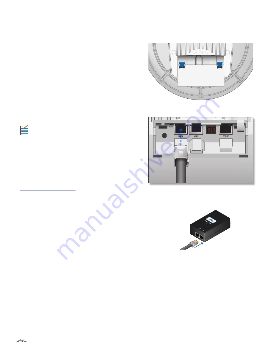
Connecting Power over Ethernet
1. Press down on the indicator arrows and slide the
Port
Cover
off.
2. Connect an Ethernet cable to the
DATA
port.
3. Connect the other end of the Ethernet cable from the
DATA
port to the Ethernet port labeled
POE
on the
PoE
Adapter
.


