background image

3

Chapter 2: Installation

airFiber

®

 X User Guide

Ubiquiti Networks, Inc.

Chapter 2: Installation

Installation Requirements

The airFiber radio operates only with the antennas listed 
below:

airFiber Radio

airFiber X Antenna

Rock Conversion Kit

AF-2X

AF-2G24-S45

n/a

AF-3X

AF-3G26-S45

n/a

AF-5X

AF-5G23-S45
AF-5G30-S45
AF-5G34-S45

RD-5G30 + AF-5G-OMT-S45
RD-5G34 + AF-5G-OMT-S45

See the antenna’s Quick Start Guide for antenna 
installation instructions. 

Other Requirements

• 

Clear line of sight between airFiber X radios

• 

Clear view of the sky for proper GPS operation

• 

Vertical mounting orientation

• 

Mounting point:

• 

At least 1 m below the highest point on the structure

• 

For tower installations, at least 3 m below the top of 
the tower

• 

Ground wires – min. 10 AWG (5 mm

2

) and max. length: 

1 m. As a safety precaution, ground the airFiber X radio 
to grounded masts, poles, towers, or grounding bars. 

WARNING:

 Failure to properly ground your 

airFiber X radio will void your warranty.


• 

(Recommended) 2 Outdoor Gigabit PoE surge protectors

Note:

 For guidelines about grounding and 

lightning protection, follow your local electrical 
regulatory codes. 

• 

Outdoor, shielded Category 6 (or above) cabling and 
shielded RJ-45 connectors are required for all wired 
Ethernet connections.

Installation Overview

We recommend to configure your paired airFiber X radios 
before site installation. The overview below summarizes 
the installation procedure, and the subsequent sections 
provide detailed installation information:

• 

Connect the airFiber PoE Adapter

 to the 

DATA port, and 

connect your computer and the MGMT port.

• 

Configure the airFiber X radio.

• 

Install a ground wire and mount the airFiber X radio on 
an airFiber X antenna.

• 

At the installation site, install the airFiber X antenna with 
the mounted airFiber X radio (see the antenna’s Quick 
Start Guide for installation instructions).

• 

Secure the ground wire and mount the GPS antenna.

• 

Establish and optimize the RF link.

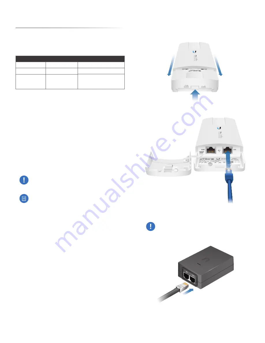
Connecting Power over Ethernet

1.  Lift the release latch on the bottom of the airFiber X 

radio and slide the 

Port Cover off.

2.  Connect an Ethernet cable to the DATA port.

3.  Connect the Ethernet cable from the DATA

 port to the 

Ethernet port labeled POE

 on the 

airFiber PoE Adapter.

WARNING:

 Use only the included airFiber PoE 

adapter, Model GP-H240-100G-4. Failure to do 
so can damage the unit and void the product 
warranty.

Содержание AF-3X

Страница 1: ...2 4 GHz 3 GHz 5 GHz Carrier Backhaul Radio Model AF 2X AF 3X AF 5X ...

Страница 2: ......

Страница 3: ...iber Configuration 4 Hardware Installation 5 Alignment 9 Installer Compliance Responsibility 10 Chapter 3 Navigation 11 Accessing the airFiber Configuration Interface 11 Product Verification 12 Interface Tabs 12 Chapter 4 Main Tab 13 Status 13 Ethernet 15 Monitor 15 Chapter 5 Wireless Tab 17 Basic Wireless Settings 17 Frequency Settings 19 Wireless Security 19 Chapter 6 Network Tab 20 Management N...

Страница 4: ...9 Location 30 Device Maintenance 30 Configuration Management 30 Chapter 10 Tools 31 Align Antenna 31 Discovery 32 Ping 32 Traceroute 32 airView 32 Appendix A Specifications 36 Appendix B Listen Before Talk 39 Introduction 39 Unrestricted Protocol Description 39 Threshold Detection To Determine Occupancy 39 Action Taken When Occupancy is Determined 39 Opportunities for Other Transmitters to Operate...

Страница 5: ... Compliance Responsibility 44 FCC 44 Industry Canada 45 RF Exposure Warning 47 Australia and New Zealand 47 CE Marking 47 Frequency Ranges and Power Levels per Country Region 48 RoHS WEEE Compliance Statement 53 Appendix F Declaration of Conformity 54 Appendix G Contact Information 55 Ubiquiti Networks Support 55 ...

Страница 6: ...iv Table of Contents airFiber X User Guide Ubiquiti Networks Inc ...

Страница 7: ...page 37 for more information This User Guide provides installation instructions explains how to set up an airFiber link and shows how to access and use the airFiber Configuration Interface Note Throughout this User Guide airFiber X radio refers to all models listed above Unless noted otherwise illustrations for a specific model are applicable to all airFiber X radio models and accessories Package ...

Страница 8: ...solidly on to a 2 5 Hz flash This continues until the airFiber X radio is fully booted Signal Level Once fully booted the Signal 1 4 LEDs act as a bar graph showing how close the airFiber X radio is to ideal aiming This is auto scaled based on the link range the antenna gains and the configured TX power of the remote airFiber X radio Each Signal LED has three possible states On Flashing and Off Al...

Страница 9: ...ion follow your local electrical regulatory codes Outdoor shielded Category 6 or above cabling and shielded RJ 45 connectors are required for all wired Ethernet connections Installation Overview We recommend to configure your paired airFiber X radios before site installation The overview below summarizes the installation procedure and the subsequent sections provide detailed installation informati...

Страница 10: ... the 192 168 1 x subnet 3 Launch your web browser Type http 192 168 1 20 in the address field and press enter PC or return Mac 4 The login screen will appear Enter ubnt in the Username and Password fields Select your Country and Language You must agree to the Terms of Use to use the product Click Login Note U S product versions are locked to the U S Country Code to ensure compliance with FCC regul...

Страница 11: ...ption DHCP Keep the default DHCP to use DHCP reservation on your router to assign a unique IP Address Static Change the IP Address Netmask and other settings to make them compatible with your network b Click Change and then click Apply Repeat the instructions in the airFiber Configuration section on your other airFiber X radio After you have configured the airFiber X radios disconnect them and mov...

Страница 12: ...acket b Slide the airFiber X radio down to lock it into place 2 Attach the RF cables from the antenna feed to the RF connectors on the airFiber X radio in this combination 45 to Chain 0 and 45 to Chain 1 3 Attach the External GPS Antenna to the RF connector labeled GPS Then place the magnetic External GPS Antenna on the bracket this is temporary you will mount the External GPS Antenna on the GPS A...

Страница 13: ...h the GPS Antenna Mount to the pole using the metal strap or attach it to a wall using the appropriate fasteners not included 2 Place the External GPS Antenna on the mount 3 Secure the cable of the External GPS Antenna to the mount with a Cable Tie Connecting Power over Ethernet 1 Lift the release latch on the bottom of the airFiber X radio and slide the Port Cover off 2 Connect an outdoor shielde...

Страница 14: ... labeled LAN on the airFiber PoE Adapter 5 Connect the Power Cord to the power port on the airFiber PoE Adapter Connect the other end of the Power Cord to a power source Mount the PoE Adapter Optional 1 Remove the Mounting Bracket from the adapter by sliding the bracket downward 2 Place the Mounting Bracket at the desired location and mark the holes for the fasteners Pre drill the holes if necessa...

Страница 15: ...dditional hardware to compensate for issues such as the improper orientation of a mounting pole or significant elevation differences between airFiber X radios Establishing a Link Adjust the positions of the Master and the Slave to establish a link Note The Master must be aimed first at the Slave because the Slave does not transmit any RF signal until it detects transmissions from the Master Note T...

Страница 16: ...ith all four Signal LEDs solidly lit This ensures the best possible data rate between the airFiber X radios 7 Lock the alignment on both airFiber antennas by tightening all the nuts and bolts 8 Observe the Signal LEDs of each airFiber X radio to ensure that the values remain constant while tightening the nuts and bolts If any LED value changes during the locking process loosen the nuts and bolts f...

Страница 17: ...Network Settings on page 20 for more details Accessing the airFiber Configuration Interface Connect to the airFiber Configuration Interface 1 Make sure that your host machine is connected to the LAN that is connected to the Management port on the airFiber X radio 2 Configure the Ethernet adapter on your host system with a static IP address on the 192 168 1 x subnet for example 192 168 1 100 3 Laun...

Страница 18: ...isplays device status statistics and network monitoring links Wireless The Wireless Tab on page 17 configures basic wireless settings including the wireless mode link name frequency output power speed and wireless security Network The Network Tab on page 20 configures the management network settings Internet Protocol IP settings management VLAN and automatic IP aliasing Advanced The Advanced Tab o...

Страница 19: ...ration screens and discovery tools Operating Mode Displays the mode of the AirFiber X radio Slave Master or Reset RF Link Status Displays the status of the AirFiber X radio RF Off Syncing Beaconing Registering Enabling Listening Operational DFS CAC or RADAR Detected Note Most of the RF Link Statuses map to specific flash rates of the Link Status LED See LEDs on page 2 for more details Status Flash...

Страница 20: ...urate if the NTP Client is disabled or the device isn t connected to the Internet Frequency Available if split frequencies are not enabled Displays the current frequency The AirFiber X radio uses the radio frequency specified to transmit and receive data TX Frequency Available if split frequencies are enabled Displays the frequency that the airFiber X radio uses to transmit data RX Frequency Avail...

Страница 21: ...the Ethernet cable length from radio to remote port This is displayed only for cables longer than 20 m DATA Pair 0 Pins 1 2 If the cable is functioning properly displays the SNR of the twisted pair if the cable has a fault displays the fault open or short and the distance at which the fault has occurred If the remote port is administratively shut down this field displays normal DATA Pair 1 Pins 3 ...

Страница 22: ... Inc Log When logging is enabled see System Log on page 27 to enable logging this option lists all registered system events By default logging is not enabled Clear To delete all entries in the system log click Clear Refresh To update the log content click Refresh ...

Страница 23: ... and resumes its earlier configuration Discard To cancel your changes click Discard Write down the settings you configure on the Wireless tab You will need to enter the same settings on the airFiber X radio at the other end of your PtP link The exceptions are as follows Wireless Mode Configure one airFiber X radio as the Master and the other as the Slave Basic Wireless Settings In this section con...

Страница 24: ... or manually enter the output power value The transmit power level maximum is limited according to country regulations Note The Antenna Gain and Cable Loss should be configured before the Output Power This is because the range of the Output Power field is affected by the Antenna Gain and Cable Loss values changing the antenna gain or cable loss adjusts the maximum and minimum values you can select...

Страница 25: ...egions where both DFS and non DFS frequencies are available enabling split frequencies will disable any DFS band frequencies In regions where only DFS frequencies are available there will be no option to turn on split frequencies Frequency Enter a valid frequency The current state is displayed Note The Master and Slave should have the same Frequency setting Wireless Security airFiber uses 128 bit ...

Страница 26: ...gh the local Data port or the Data port at the other end of the link Note If In Band Management is enabled ensure that each airFiber X radio in a link has a unique IP Address If the airFiber X radios use the same IP Address you may lose access via the Data ports Management IP Address The airFiber X radio can use a static IP address or obtain an IP address from its DHCP server DHCP Keep the default...

Страница 27: ...the primary DNS server is not responding Management VLAN If enabled automatically creates a management Virtual Local Area Network VLAN VLAN ID Enter a unique VLAN ID from 2 to 4094 Auto IP Aliasing If enabled automatically generates an IP address for the corresponding WLAN LAN interface The generated IP address is a unique Class B IP address from the 169 254 X Y range netmask 255 255 0 0 which is ...

Страница 28: ...bled Automatic Power Backoff This feature allows the radio to automatically adjust the maximum TX power per modulation so that the radio never transmits at a higher power than each modulation rate can decode The default values in the Max 8x 6x 4x Conducted Power fields are values determined to work at all temperatures and all frequencies supported by the radio It may however be possible to increas...

Страница 29: ...timers control the Data port s Ethernet link RF Link Ethernet Link Notes Goes down for the first time The Ethernet link goes down and remains down for the number of seconds specified by the Link Off Duration timer The Ethernet link will then come back up so that the airFiber X radio can be managed even when the RF link is down Even if the RF link goes back up before the Link Off Duration timer ela...

Страница 30: ...ns down until the RF link goes back up Minimum TX Capacity This is the minimum allowable TX capacity before the link is dropped If the capacity drops below this threshold the Ethernet link will be dropped If set to 0 then capacity will not be used only the RF link state will be used Minimum RX Capacity This is the minimum allowable RX capacity before the link is dropped If the capacity drops below...

Страница 31: ... configuration Discard To cancel your changes click Discard Ping Watchdog Ping Watchdog sets the airFiber X radio to continuously ping a user defined IP address it can be the Internet gateway for example If it is unable to ping under the user defined constraints the airFiber X radio will automatically reboot This option creates a kind of fail proof mechanism Ping Watchdog is dedicated to continuou...

Страница 32: ...unity string It is required to authenticate access to Management Information Base MIB objects and functions as an embedded password The airFiber X radio also supports a read only community string authorized management stations have read access to all the objects in the MIB except the community strings but do not have write access The airFiber X radio supports SNMP v1 The default SNMP Community is ...

Страница 33: ...ugh its domain name Dynamic DNS If enabled the airFiber X radio allows communications with the DDNS server Host Name Enter the host name of the DDNS server Username Enter the user name of the DDNS account Password Enter the password of the DDNS account Show Check the box to display the password characters System Log System Log This option enables the registration routine of system log syslog messa...

Страница 34: ...down is displayed the airFiber X radio times out and resumes its earlier configuration Discard To cancel your changes click Discard Firmware Update The controls in this section manage firmware maintenance Firmware Version Displays the current firmware version Build Number Displays the build number of the firmware version Check for Updates By default the firmware automatically checks for updates To...

Страница 35: ...e Click the Calendar icon or manually enter the date in the following format 2 digit month 2 digit day 4 digit year For example for January 5 2014 enter 01 05 2014 in the field System Accounts You can change the administrator password to protect your device from unauthorized changes We recommend that you change the default administrator password when initially configuring the device Administrator ...

Страница 36: ...heir request Configuration Management The controls in this section manage the airFiber X radio configuration routines and the option to reset the airFiber X radio to factory default settings The airFiber X radio configuration is stored in a plain text file cfg file You can back up restore or update the system configuration file Back Up Configuration Click Download to download the current system co...

Страница 37: ...deal Displays the absolute power level in dBm of the received signal for each chain Note If Overload is displayed to indicate an overload condition identify and eliminate any sources of strong in band interference Remote Chain 0 1 Actual Ideal Displays the absolute power level in dBm of the received signal for each chain of the remote airFiber X radio Max Signal Displays the maximum signal strengt...

Страница 38: ... of the packet Start Click this button to start the test Packet loss statistics and latency time evaluation are displayed after the test is completed Traceroute The Traceroute tool traces the hops from the airFiber X radio to a specified outgoing IP address Use this tool to find the route taken by ICMP packets across the network to the destination host Destination Host Enter the IP address of the ...

Страница 39: ...d in Preferences This time based graph shows the aggregate energy collected or channel usage for each frequency since the start of the airView session Enable Chart Panel 2 middle Displays the Waveform chart in Chart Panel 2 This time based graph shows the RF signature of the noise environment since the start of the airView session The energy color designates its amplitude Cooler colors represent l...

Страница 40: ...t related to Wi Fi channels which are determined by IEEE standards airFiber X radio channels are numbered consecutively starting with 0 and are 28 MHz in width Enable Waveform chart middle Check the box to enable the middle chart This time based graph shows the RF signature of the noise environment since the start of the airView session The energy color designates its amplitude Cooler colors repre...

Страница 41: ... the maximum power trace When enabled the maximum power trace is represented by the blue area on the Real time chart which displays the maximum received power level data since the start of the airView session To enable a shaded blue area check the Shaded Area box To display only a blue outline without the shaded area uncheck the Shaded Area box Frequency Range Select the amplitude of the frequency...

Страница 42: ...ket Mount Compatible GPS Pole Mount Included Certifications FCC Part 15 247 CE EN 300328 v1 8 1 Operating Temperature 40 to 55 C 40 to 131 F Networking Interface Data Port 1 10 100 1000 Ethernet Port Management Port 1 10 100 Ethernet Port System Maximum Throughput 500 Mbps Encryption 128 bit AES OS airOS F Wireless Modes Master Slave Radio Operating Frequency 2400 2500 MHz Depends on Regulatory Re...

Страница 43: ...ompatible GPS Pole Mount Included Certifications FCC Part 90 Z CE EN 302 217 2 2 Operating Temperature 40 to 55 C 40 to 131 F Networking Interface Data Port 1 10 100 1000 Ethernet Port Management Port 1 10 100 Ethernet Port System Maximum Throughput 500 Mbps Encryption 128 bit AES OS airOS F Wireless Modes Master Slave Radio Operating Frequency 3300 3900 MHz Depends on Regulatory Region Frequency ...

Страница 44: ...ocket Mount Compatible GPS Pole Mount Included Certifications FCC Part 15 407 CE EN 302502 v1 2 1 EN 301 893 v1 7 1 Operating Temperature 40 to 55 C 40 to 131 F Networking Interface Data Port 1 10 100 1000 Ethernet Port Management Port 1 10 100 Ethernet Port System Maximum Throughput 500 Mbps Encryption 128 bit AES OS airOS F Wireless Modes Master Slave Radio Operating Frequency 5150 5950 MHz Depe...

Страница 45: ...ver s input assuming antenna gain of 0 dBi is 73 dBm MHz The detection threshold is adjusted as follows DT 73 dBm MHz 10log10 B 23 PT A where DT Detection Threshold in dBm B Monitored bandwidth in MHz PT Maximum transmit power in dBm EIRP A Receive antenna gain in dBi The receive antenna gain A is set equal to the external antenna gain The following are set by the operator during the configuration...

Страница 46: ...amount of bandwidth is reserved for channel detection so performance remains unaffected If there are two AF 3X systems on a co channel they would share the spectrum as follows Since the system is a synchronized frame based system both systems would operate effectively with each other because each system can be configured to transmit and receive at the same point in time The system uses a GPS synch...

Страница 47: ...s inside this equipment Service should be provided only by a qualified service technician 3 This equipment is provided with a detachable power cord which has an integral safety ground wire intended for connection to a grounded safety outlet a Do not substitute the power cord with one that is not the provided approved type Never use an adapter plug to connect to a 2 wire outlet as this will defeat ...

Страница 48: ... 5 for installation of the ground wires Returns No Products will be accepted for replacement or repair without obtaining a Return Materials Authorization RMA number from UBIQUITI NETWORKS during the warranty period and the Products being received at UBIQUITI NETWORKS facility freight prepaid in accordance with the RMA process of UBIQUITI NETWORKS Products returned without an RMA number will not be...

Страница 49: ...provinces do not allow exclusions of implied warranties or conditions so the above exclusion may not apply to you You may have other rights that vary from country to country state to state or province to province Some countries states and provinces do not allow the exclusion or limitation of liability for incidental or consequential damages so the above limitation may not apply to you EXCEPT TO TH...

Страница 50: ...tenna impedance for each antenna type indicated Antenna types not included in this list having a gain greater than the maximum gain indicated for that type are strictly prohibited for use with this device Dish antenna gain 6 dBi Dish antenna gain 24 dBi airFiber AF 3X Changes or modifications not expressly approved by the party responsible for compliance could void the user s authority to operate ...

Страница 51: ...latory Regions Operation in DFS regulatory regions requires an antenna with minimum gain of 23 dBi Industry Canada airFiber AF 2X CAN ICES 3 B NMB 3 B To reduce potential radio interference to other users the antenna type and its gain should be so chosen that the equivalent isotropically radiated power e i r p is not more than that permitted for successful communication This device complies with I...

Страница 52: ...rmis en dBi et requis d impédance pour chacun Antenne parabolique gain 12 dBi Antenne parabolique gain 26 dBi Antenne parabolique gain 29 dBi airFiber AF 5X CAN ICES 3 B NMB 3 B To reduce potential radio interference to other users the antenna type and its gain should be so chosen that the equivalent isotropically radiated power e i r p is not more than that permitted for successful communication ...

Страница 53: ... operating in conjunction with any other antenna or transmitter Les antennes utilisées pour ce transmetteur doivent être installé en considérant une distance de séparation de toute personnes d au moins 126 cm et ne doivent pas être localisé ou utilisé en conflit avec tout autre antenne ou transmetteur Australia and New Zealand airFiber AF 2X Warning This is a Class B product In a domestic environm...

Страница 54: ...zil 2400 2483 36 Canada 2400 2483 36 Chile 2400 2483 36 China 2400 2483 36 Colombia 2400 2483 36 Ecuador 2400 2483 36 Ghana 2400 2483 36 Guam U S territory 2400 2483 36 Hong Kong 2400 2483 36 Indonesia 2400 2483 36 India 2400 2483 36 Kenya 2400 2483 36 Korea Republic 2400 2483 36 Kyrgyzstan 2400 2483 Not applicable Malaysia 2400 2483 36 Mexico 2400 2483 36 New Zealand 2400 2483 36 Nigeria 2400 248...

Страница 55: ...n Country Region Frequency Range Band Edges in MHz Max EIRP dBm Austria 3410 3900 66 Belgium 3410 3900 66 Bulgaria 3410 3900 66 Canada 3450 3650 3650 3700 57 44 Croatia 3410 3900 66 Cyprus 3410 3900 66 Czech Republic 3410 3900 66 Denmark 3410 3900 66 Estonia 3410 3900 66 Finland 3410 3900 66 France 3410 3900 66 Germany 3410 3900 66 Greece 3410 3900 66 Guam U S territory 3650 3700 44 Hungary 3410 3...

Страница 56: ...Hz Max EIRP dBm Argentina 5150 5250 49 5470 5725 30 5725 5850 36 Australia 5470 5600 5650 5725 30 5725 5855 36 Bahrain 5735 5835 20 Barbados 5725 5850 36 Belize 5735 5835 30 Bolivia 5735 5835 30 Brazil 5470 5725 30 5725 5850 53 Brunei Darussalam 5735 5835 20 Canada 5250 5350 30 5470 5600 5650 5725 30 5725 5850 60 Chile 5250 5350 30 5735 5835 20 China 5735 5835 30 Colombia 5250 5350 30 5735 5835 30...

Страница 57: ...30 Panama 5735 5835 30 Papua New Guinea 5735 5835 30 Peru 5150 5250 49 5250 5350 30 5470 5725 30 5725 5850 36 Philippines 5150 5250 49 5250 5350 30 5470 5725 30 5725 5850 36 Portugal 5470 5725 30 5725 5875 36 Puerto Rico U S territory 5250 5350 30 5470 5600 5650 5725 30 5725 5850 60 Qatar 5735 5835 30 Russia 5150 5350 43 5470 5650 23 5650 5950 53 Singapore 5735 5835 30 South Africa 5470 5725 30 57...

Страница 58: ...nd Maximum Transmit Output Power EIRP in dBm Channel Bandwidth Frequency Range Band Edges in MHz 10 MHz 5155 5175 39 5166 5186 44 5177 5250 49 20 MHz 5156 5180 37 5161 5185 39 5166 5209 44 5190 5250 49 30 MHz 5155 5192 37 5163 5202 39 5173 5211 44 5182 5250 49 40 MHz 5155 5204 37 5165 5219 39 5180 5228 44 5189 5250 49 50 MHz 5155 5214 37 5165 5233 39 5184 5242 44 5193 5250 49 ...

Страница 59: ...ricos y electrónicos a través de los puntos de recogida que ponen a su disposición el gobierno y las autoridades locales Al desechar y reciclar correctamente estos aparatos estará contribuyendo a evitar posibles consecuencias negativas para el medio ambiente y la salud de las personas Si desea obtener información más detallada sobre la eliminación segura de su aparato usado consulte a las autorida...

Страница 60: ...ér UBIQUITI NETWORKS því yfir að þetta UBIQUITI NETWORKS tæki er í samræmi við grunnkröfur og önnur viðeigandi ákvæði tilskipun 1999 5 EC Italiano Italian Con la presente UBIQUITI NETWORKS dichiara che questo dispositivo UBIQUITI NETWORKS è conforme ai requisiti essenziali ed alle altre disposizioni pertinenti della direttiva 1999 5 CE Latviski Latvian Ar šo UBIQUITI NETWORKS deklarē ka UBIQUITI N...

Страница 61: ...nd the world and are dedicated to helping customers resolve software hardware compatibility or field issues as quickly as possible We strive to respond to support inquiries within a 24 hour period Ubiquiti Networks Inc 2580 Orchard Parkway San Jose CA 95131 www ubnt com Online Resources Support support ubnt com Community community ubnt com Downloads downloads ubnt com AI101615 ...

Страница 62: ...biquiti Networks the Ubiquiti U logo the Ubiquiti beam logo airFiber airOS RocketDish TOUGHCable and xRT are trademarks or registered trademarks of Ubiquiti Networks Inc in the United States and in other countries All other trademarks are the property of their respective owners ...

Отзывы: