9
Chapter 2: Installation
airFiber
®
X User Guide
Ubiquiti Networks, Inc.
Surge Protection
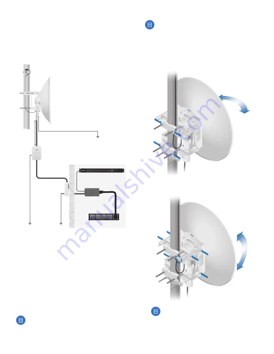
For added protection, install two surge suppressors, such
as the Ubiquiti Ethernet Surge Protector, model ETH-SP,
at the end of each link. Install the first surge protector
within one meter of the airFiber DATA port, and install the
second surge protector at the ingress point of the location
housing the wired network equipment.
Ground to Pole, Tower,
or Grounding Block:
Max. 1 m from AF-5X
M
ax. 1 m
airFiber
PoE Adapter
EdgeRouter
™
Power Source
ETH-SP
GPS Antenna
ETH-SP
AF-5X
Mounted on
AF-5G30-S45
Alignment
Tips
•
To accurately align the airFiber X radios for best
performance, you MUST align only one end of the link at
a time.
•
You may need to use additional hardware to
compensate for issues such as the improper orientation
of a mounting pole or significant elevation differences
between airFiber X radios.
Establishing a Link
Adjust the positions of the Master
and the
Slave
to
establish a link.
Note:
The
Master must be aimed first at the Slave
because the Slave does not transmit any RF signal
until it detects transmissions from the Master.
Note:
The airFiber X antenna AF-5G30-S45 is
shown in the following steps. Instructions for other
antennas are similar. For complete details, refer to
the Quick Start Guide for your specific model.
1.
Master
Visually aim the Master
at the
Slave. To adjust
the
Master’s position:
a. Loosen the four pole clamp nuts, and rotate the
airFiber antenna on the pole to align the azimuth.
b. Loosen the six elevation bolts, and use the hex nut
on the elevation rod to adjust the elevation.
Note:
Do NOT make simultaneous adjustments
on the
Master
and
Slave.
Содержание AF-3X
Страница 1: ...2 4 GHz 3 GHz 5 GHz Carrier Backhaul Radio Model AF 2X AF 3X AF 5X ...
Страница 2: ......
Страница 6: ...iv Table of Contents airFiber X User Guide Ubiquiti Networks Inc ...


