background image

1

revised 09/09

Smog-Hog

SG Series Model

1. HOW THE SMOG-HOG SG SERIES 

WORKS 

   the SG is a self-contained air cleaning system which 

removes dry or oily airborne con taminants from 

industrial work areas.  operating on the principle of 

electrostatic precipitation, it pulls air past a mechanical 

prefilter, charges and collects airborne particulate, then 

exhausts clean air to the  environment.

   Prefilters serve the dual purpose of trapping large 

 particulate and diffusing the airstream evenly into 

 precipitator components at low, controlled velocity.  

air passes through an ionizing section, where nearly 

all particulate is charged, then on to a collecting 

 section where charged particles are repelled from 

similarly charged plates and drawn to ground plates.  

agglomerated particles separated from collection plates 

during unit start-up are trapped on an after filter, allowing 

clean air to pass through the system blower at all times.

   SG units may be ducted directly to the  contaminant 

source or unducted to remove particulate from the 

general environment.  units are gen erally suspended 

from the ceiling but may be cradle or skid mounted to 

suit the application.  units without blowers are supplied 

where air is moved through the units by others.

   The Smog-Hog SG uniquely combines high airflow 

and high efficiency.  its compact “unicell” design 

helps minimize contaminant by-pass.  it is suitable for 

operation with or without in-place cleaning.  all SG units 

supplied with blowers have ad justable louvers to direct 

exhaust air as required.

   ionizing and collecting sections operate on high Dc 

(direct current) voltage and low amperage, yielding a 

very low power consumption of 75 watts maximum per 

power supply.  the high voltage creates a  powerful field 

for trapping small to submicronic  particles.  at start-up, 

the unit’s power supply charges each unicell while the 

system blower begins to move air through the unit.

2. INSPECTION OF EQUIPMENT

   upon receipt of your SMoG-HoG SG, check carefully 

for possible shipping damage. (any damage to  carton, 

skid, etc., may be a warning to you that rough handling 

has caused internal damage.) units supplied with 

accessories, such as an in-Place cleaning System, 

will arrive in multiple cartons.  check cartons versus 

bill of lading.  the detergent container is shipped 

independent of units. 

   notify your delivery carrier and enter a claim if any 

damage is found.  

3. INSTALLATION PLANNING

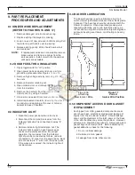
3.1 UNDUCTED OR AREA CAPTURE

   consideration should be given to the placement of the 

precipitator to maximize its effectiveness.  The number 

of units required to clean the air will depend on the 

layout of the room and the con centration of pollutants.

   Because it is necessary to develop proper airflow patterns, 

the placement and number of precip itators should be as 

suggested by uaS or your local representative.

3.2 DUCTED OR SOURCE CAPTURE 

   When your SG is used as a ducted source collector, 

the enclosure or pick-up hood design is important for 

adequate capture of con taminants.  Drive pulleys and 

belts have been selected to provide proper airflow at 

the design static pressure specified.  Pulleys and belts 

should not be replaced without first contacting uaS 

customer Service at 1-800-252-4647.

3.3 SPECIFICATIONS 

   Smog-Hog SG Series are self-contained, two-stage, 

Penney-type, electrostatic precipitators complete 

with fully interlocked, energy limiting uL “recognized 

component” power packs, mechanical prefilters, unicell 

construction (combination ionizer and collection cell), 

afterfilters, indicator lights and interlock switches.  all 

models except those designated “X” are  supplied 

with motor/blower sets mounted in an integral blower 

housing.  All high voltage wiring is external to the 

component enclosure. 

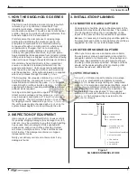
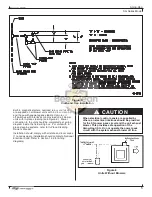
Figure 1

SG SERIES NOMENCLATURE

H   HiGH PreSSure
M   tanDeM
a   in PLace cLeaninG

S   StacKeD (2 on 2) ceLL 

 confiGuration

t   tee SHaPeD confiGuration
X   WitHout BLoWer

2  tWo uniceLLS
4  four uniceLLS
6  SiX uniceLLS

SMoG-HoG SerieS

Содержание SMOG-HOG SG-2-A

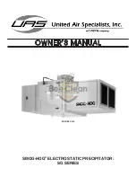
Страница 1: ...OWNER S MANUAL SMOG HOG ELECTROSTATIC PRECIPITATOR SG SERIES MODEL SG 2 ...

Страница 2: ... contacting UAS UAS ORDER _________________________________________________________________ UNIT MODEL ________________________________________________________________ UNIT SERIAL _________________________________________________________________ HIGH VOLTAGE POWER PART NUMBER _ _________________________________________ SYSTEM ACCESSORIES ____________________________________________________________...

Страница 3: ...5 4 Motor Variable Pitch Pulley Adjustment 7 5 5 Blower Belt Tension Adjustment 7 5 6 Power Pack Operation 7 5 7 Power Pack Enclosure Push Rod and Grounding Bar 8 5 8 In Place Cleaning Optional 8 5 9 Placing SG On Line 9 6 MAINTENANCE AND MANUAL CLEANING 9 6 1 Normal Maintenance 9 6 1 1 Check Power Pack Enclosure Indicator Lights 9 6 1 2 Check Component Appearance Weekly 9 6 1 3 Perform In Place C...

Страница 4: ...ii ...

Страница 5: ...rough Insulators 12 9 3 Indicator Light 12 9 4 Blower Lubrication 12 9 5 Component Access Door Gasket Replacement 12 9 6 Power Pack Enclosure Push Rod Adjustment 13 10 TROUBLESHOOTING 14 10 1 Troubleshooting Procedure 14 10 2 High Voltage Probe Measurements 17 10 3 Bench Test Procedure 17 10 4 Troubleshooting Guide 19 11 ORDERING PARTS 21 11 1 Replacement Parts 21 11 2 Returning Parts 21 11 3 Frei...

Страница 6: ...eres Use non flammable cleaners Keep flammable materials and vapors such as gasoline away from the unit The unit should be inspected frequently and contaminants removed to prevent excessive accumulation which may result in flash over or fire damage Operate only in a safe and serviceable condition Operating temperature to the air stream should not exceed 120 F DANGER WARNING WARNING CAUTION C A U T...

Страница 7: ...lower begins to move air through the unit 2 INSPECTION OF EQUIPMENT Upon receipt of your SMOG HOG SG check carefully for possible shipping damage Any damage to carton skid etc may be a warning to you that rough handling has caused internal damage Units supplied with accessories such as an In Place Cleaning System will arrive in multiple cartons Check cartons versus bill of lading The detergent con...

Страница 8: ...2 Revised 09 09 Smog Hog SG Series Model MODEL SG 2 MODEL SG 4S ...

Страница 9: ...3 Revised 09 09 Smog Hog SG Series Model MODEL SG 4T MODEL SG 6 Figure 2 Installation Dimensions in cm ...

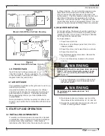
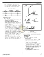
Страница 10: ... Ceiling Mounting SG units are designed for suspended mounting using 1 2 all thread rod as shown in Figure 4 Customer should take care to ensure that roof trusses are adequate to support unit weight and support members In Figure 4 angle iron cross members are secured between roof trusses Turnbuckles greatly simplify rod installation Rod length should be kept to a minimum 36 preferred All SG units ...

Страница 11: ...with in place cleaning systems refer to In Place Cleaning Owner s Manual Installation should comply with all state and local codes If no codes apply installation should comply to National Electrical Code Refer to Section 12 2 for wiring diagrams Figure 5 Drain and Trap Installation CAUTION When electrical control panels are supplied by others an electrical interlock should be provided for the SG p...

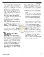
Страница 12: ...as pre and after filters if the SG is not equipped with In Place Cleaning The SG inlet plenum if supplied by UAS could have filter media or impingement filters The inlet plenum should be inspected that all filters are installed 5 2 Blower Rotation For proper airflow the blower should be operating in the correct direction If the blower is operating in the reverse direction air will move in the prop...

Страница 13: ...leys using straight edge and square 9 Set belt tension using a belt tension gage Improper blower speeds adversely affect system performance Contact the factory before adjusting motor variable pulley setting 5 5 Blower Belt Tension Adjustment The drive belt tension adjustment is critical within the first 24 hours of the system exhaust blower operation During this 24 hour period the initial stretch ...

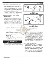
Страница 14: ... limit switch 4 refer to Figure 11 Upon opening the component door 10 the push rod 5 is released from the unicell endplate 6 and spring 7 compression is relieved breaking the contact of the push rod extension 1 from the ground bar 2 placing AC voltage off line to the power pack and causing the grounding bar to contact the acorn nut 8 refer to Figure 12 When opening the power pack door 3 the spring...

Страница 15: ...ry system equipment refer manufacturer s owner s instructions for proper operating procedures 6 MAINTENANCE AND MANUAL CLEANING Figure 14 Grounding the Collecting Section Figure 15 Grounding the Ionizing Section CAUTION The SG unit should be inspected frequently and collected contaminant removed from the system regularly to prevent excessive accumulation which may result in a flashover or risk of ...

Страница 16: ...a cleaning solution per the detergent manufacturer s directions More or less detergent may eventually be required for effective cleaning at reasonable detergent cost The recommended factory detergent concentration is 5 20 1 CAUTION Never mix caustic and alkaline detergents for manual or in place cleaning Detergent mixing could cause rapid heat release gel formation or some other undesirable condit...

Страница 17: ...ffective cleaning including water heating detergent injection agitation rinsing and drying 7 4 Other Cleaning Considerations The previous methods address the cleaning of unicells and filter media The SG cabinet should also be periodically cleaned i e during normal planned downtimes to reduce contaminant build up High voltage output of the power packs should also be checked when manual cleaning is ...

Страница 18: ...light which is connected to wires 9 and 2 3 Remove indicator light installation nut The indicator light located on each power pack enclosure is polarity sensitive For proper operation the two wires from the indicator light should be connected as follows red wire connected to 9 wire from the power pack black wire connected to 2 wire from the power pack If the wires are reversed the indicator light ...

Страница 19: ...ove existing gasket making sure to scrape off any residual silicone sealant 2 Trim one edge of gasket neatly and evenly 3 The door gasket internally has three lips to one side of the gasket and one lip to the other side The door gasket should be installed with the three lips towards the interior of the cabinet 4 The door gasket should be formed to the complete cabinet flange before applying silico...

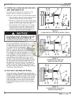
Страница 20: ...ge circuits to the ionizer and collector should be grounded before removing the power pack high voltage wires door feed through insulators and unicell s The grounding procedure can be accomplished by waiting one minute after placing the toggle switch in off position or by referring to Figures 14 and 15 An internal resistor within the power pack discharges the residual high voltage The grounding pr...

Страница 21: ...ting the high voltage wires from contacting the power pack connectors Place the toggle switch in the on position and engage interlock switch the indicator light should be illuminated If the indicator light is illuminated the power pack is operational proceed to step 2 If the indicator light is flashing high voltage wires 8 and 7 disconnected from the power pack the power pack requires replacement ...

Страница 22: ...ntacting the opposing cell plate s Warped cell plate s which could be due to high duct operating temperature consult UAS Carbon tracking to the cell high voltage feed through insulator and or cell triangular insulators imbedded black streak which cannot be removed by cleaning replace insulator Surface oxidation to unicell component requiring a replacement Unicell is structurally weak loose steel r...

Страница 23: ...Bench Testing may also be required Low ionizer voltage will decrease the collector cell voltage but low cell voltage will not affect the ionizer voltage 4 Engage the interlock switch and place the tip of the high voltage probe to the collector cell door feed through insulator bolt The high voltage measurement should be 5 0 to 7 3 KVDC If the collector cell voltage is below specifications refer ste...

Страница 24: ...nect the other high voltage wire use as a ground wire to the metal frame of the unicell cell and to the ground stud on the power pack 4 AC cable should be connected to the power pack connectors 5 and 6 with ground wire secured to the ground stud on the power pack 5 Connect AC cable plug to the wall outlet 6 Measure high voltage with the high voltage probe at the contact spring cell Collector cell ...

Страница 25: ... not properly electrically aligned Unicell s have a moderate to extreme contaminant build up Power pack has failed Power pack enclosure s push rod assembly is not properly adjusted Fuses have failed to the power pack circuit Unicells are not properly electrically aligned Air volume ACFM is not within specifications RECOMMENDED SOLUTIONS Place disconnect switch in the on on position Press the unit ...

Страница 26: ...ULATOR ASSEMBLIES 2 37 0026 INSULATOR ONLY 2 6 37 0028 IONIZER STANDOFF INSULATOR 4 7 03 0559 IONIZER WIRE SPRING 20 8 03 0738 IONIZER WIRE 10 MIL SST 10 9 30 0387 CELL CONTACT SCREW 1 10 30 0384 FLAT WASHER 1 4 SST 1 11 36 0012 CELL CONTACT SPRING 1 12 37 0061 CELL TRIANGULAR INSULATOR 8 13 10 0158 WIDE PLATE GND 37 14 10 0157 NARROW PLATE 38 15 36 0012 GROUND SPRING DOOR 1 16 36 0142 SCREW 8 32 ...

Страница 27: ...4647 For prompt service please specify 1 Unit Model No nameplate 2 Unit Serial No nameplate 3 Part No or Part Description see Illustrated Parts 11 2 ReTURNING Parts When returning parts directly to UAS call UAS for a return material authorization number RMA This number should be on the package being returned This assures prompt handling and service Replacement parts are listed in Figure 20 11 3 FR...

Страница 28: ...ng Diagram SG Standard Units Without Cleaning Magnetic Starter NOTE CUSTOMER TO PROVIDE STARTER WITH PUSH BUTTON STATION BETWEEN TERMINALS AND 1 7 LEGEND WIRING BY CUSTOMER H SUPPLIED BY CUSTOMER H H OPTIONAL START STOP STATION TERMINAL IN ELECTRICAL BOX u SG 4T UNITS ONLY 12 APPENDIX 12 1 WiRING DIAGRAMS ...

Страница 29: ...STATION BETWEEN TERMINALS AND 1 7 LEGEND WIRING BY CUSTOMER H SUPPLIED BY CUSTOMER H H OPTIONAL START STOP STATION TERMINAL IN ELECTRICAL BOX u SG 4T UNITS ONLY 12 1 WiRING DIAGRAMS Wiring Diagram SG Agency Certified Units Without Cleaning Manual Starter Wiring Diagram SG Power Pack Enclosure ...

Страница 30: ...9 Smog Hog SG Series Model 16 17 12 13 15 35 4 28 26 29 34 19 22 18 24 25 23 1 20 21 31 30 27 31 1 32 33 8 1 5 7 6 2 3 9 10 11 14 12 3 Remote Start Stop Assembly 20 3032 optional 12 2 POWer pack enclosure illustration ...

Страница 31: ...bly 2 37 0026 Door Feed Through Insulator 2 19 30 0398 Round Head Screw 10 32 x 4 SST 2 20 30 0412 Lock Washer 10 EXT Tooth SST 2 21 30 0367 Fender Washer x 1 1 2 SST 2 22 35 0013 Spacer 2 23 30 0310 Pal Nut 5 8 16 2 24 30 0003 Hex Nut 10 32 x 1 4 25 30 0249 Hex Cap Nut 10 32 SST 2 26 20 1239 Interlock Switch SPST N O 1 27 10 1077 Mounting Switch Bracket L R 1 10 1076 Mounting Switch Bracket R L 1...

Страница 32: ... wear and tear This warranty will be void with respect to equipment that is subject to unauthorized repairs or modifications UAS makes no warranty as to goods manufactured or supplied by others This warranty is subject to any limitations in UAS quotation and may not be modified except by a written instrument signed by the President or Vice President of Sales of UAS THIS WARRANTY IS EXCLUSIVE AND I...

Отзывы: