


11
revised 09/09
Smog-Hog
SG Series Model
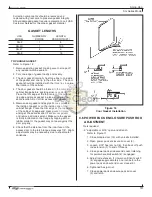
6.2.7 DRY-OUT TIME
unicells and filter media should be dry before the SG
is placed into operation. Startup of a wet system will
cause dead short conditions to the ionizer and collector
cell circuits. Wet unicells and filter media should be
placed in a warm room for drying. Techniques such
as hand wiping insulators and blow drying unicells and
filter media with compressed air will decrease drying
time. another method for drying cleaned components
is installing the unicells and filter media in the SG and
placing on the system blower on line, with all power
pack enclosure toggle switches placed in the “off”
position for 30 minutes.
7. MANUAL CLEANING METHODS
the manual cleaning method selected will depend
on the type of contaminant, rate of deposit, facility
limitations such as cleaning time windows (process
downtime) and available utilities. all cleaning methods
listed in this section are acceptable.
7.1 SOAK TANK
this method involves placing unicells and filter media
in an agitated solution of hot water and detergent and
is the most effective method. With proper detergent
selection, this procedure will quickly remove most
contaminants. unicells and filter media should not be
placed in highly concentrated detergent solutions or
allowed to soak for extended periods, (e.g., overnight),
especially at elevated temperatures. Extended soaking
(e.g., days) in solvent or detergent solution will
degrade components over time and should be avoided.
7.2 PORTABLE PRESSURE WASHER
a self-contained pressure washer with a spray wand
can be an effective cleaning method, providing it is
used with caution. Care should be taken not to expose
the unicells to close-up and prolonged blasts of high
pressure/temperature, causing cell plate deformity,
requiring a replacement set of unicells and filter media.
7.3 AUTOMATIC PARTS WASHERS
certain commercially available units combine and
automate the features necessary for effective cleaning,
including water heating, detergent injection, agitation,
rinsing and drying.
7.4 OTHER CLEANING CONSIDERATIONS
the previous methods address the cleaning of
unicells and filter media. the SG cabinet should also
be periodically cleaned (i.e., during normal planned
downtimes) to reduce contaminant build up. High
voltage output of the power packs should also be
checked when manual cleaning is performed.
8. APPEARANCE OF COMPONENTS
AFTER CLEANING
components should have a clean, not necessarily
“new,” aluminum appearance. Moderate discoloration
will not affect system efficiency. checklist for acceptable
components.
8.1 UNICELL
1. frame, end plates and cell plates are free of
contaminant build-up (residual contaminant has
been removed between plates and at comer
supports).
2. The frame is square, cell plates are parallel and
cell hot plates are centered between ground
plates.
3. ionizer standoff insulators and cell triangular
insulators are cleaned (no residual coating).
cracked or carbon-tracked insulators have been
replaced.
4. ionizing wires and springs are intact and taut,
centered between plates and free of coatings.
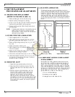
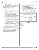
5. contact springs and contact screws are properly
located, and replace missing contact hardware.
refer to figure 20.
6. contact springs are not deformed.
7. Bent or broken parts have been repaired or
replaced.
8.2 PRE-FILTERS/AFTER-FILTERS
1. aluminum media and frame are free of
contaminant.
2. Frame is square and media is intact.
3. filters are always installed with drain holes down
and arrow on each frame pointing in the direction
of airflow
8.3 CABINET
1. Door feed-thru insulators are cleaned and white.
2. Door gaskets are cleaned and intact.
3. component tracks are free of contaminant build up
(for unicell grounding).
4. Module drain sumps are cleaned and free-flowing.
5. Interior is free of extreme contaminant build-up.
6. Blower wheel and housing is free of extreme
contaminant build-up.
7. Preconditioning equipment, if so equipped, (inlet
plenum with baffle filters, cooling coils, etc.)
has been checked for excessive pressure drop,
cleaned if necessary.
8. nozzles on all in-place cleaning system headers,
if so equipped, are not plugged.