


SAFETY •
INSTALLATION & INTEGRATION
• OPERATING INSTRUCTIONS •
MAINTENANCE • SERVICE
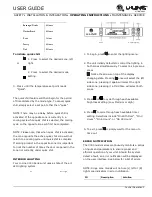
Drawers 3
USER GUIDE
u-line.com
3.
Mark new drilling holes using different sets of mounting holes on the slide.
Note:
Front location holes are shown. Corresponding rear
holes will also need to be marked.
4.
Drill all the new holes with a #30 drill bit.
5.
Remount the slide.
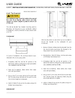
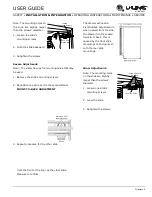
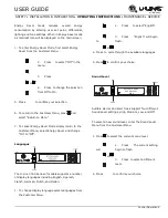
Severe Adjustment:
Note:
The slides have extra
Mark and Drill New
mounting holes that may be
Mounting Holes
used.
1.
Loosen one slide’s rear
mounting screws.
2.
Remove the slide’s fr
ont
mounting screws.
3.
Reposition the slide so it is level.
4.
Mark new front drilling holes using a different set
of mounting holes on the slide.
5.
Drill the new holes with a #30 drill bit.
6.
Remount the slide.
7.
Repeat procedure for the other slide.
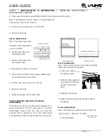
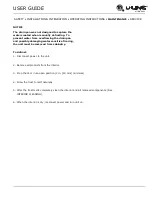
TOP-TO-BOTTOM (AND LEFT-TO-RIGHT)
ADJUSTMENT
The drawer will need a Top-to-Bottom Adjustment if,
when viewed from the front, the drawer is not level
horizontally. Viewed from the top, one side will
protrude. This is caused by one of the slides being
mounte
d higher than the other slide on the unit’s liner.
Minor Adjustment:
Note:
The mounting holes on the slide are slightly
larger than the screws’ diameter.
1.
Loosen one slide’s
Loosen
mounting screws.
2.
Push the slide upward or
downward to match the
position of the other
slide.
3.
Retighten the screws.
4.
Repeat the procedure with the other slide if
necessary.
Severe Adjustment:
Note:
The slides have extra mounting holes that
may be used. 1. Remove one slide’s
Mark and Drill New
mounting screws.
Mounting Holes
Push Slide
Upward or
Downward
Mounting Screws
Содержание 3024DWR
Страница 16: ......
Страница 21: ......
Страница 32: ...RATION USER GUIDE u line com Cleaning 1...
Страница 36: ...USER GUIDE u line com Extended Non Use 1...
Страница 41: ...SAFETY INSTALLATION INTEGRATION OPERATING INSTRUCTIONS MAINTENANCE SERVICE USER GUIDE u line com...
Страница 45: ......


