TOBY-L4 series - System Integration Manual
UBX-16024839 - R04
System description
Page 51 of 143
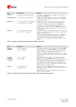
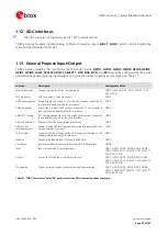
TOBY-L4 series modules "50" product versions include 9 pins (
GPIO1
,
GPIO2
,
GPIO3
,
GPIO4
,
GPIO5
,
GPIO6
,
GPIO7
,
GPIO8
, and
RI
) that can be configured by AT commands as general purpose input/output or to provide
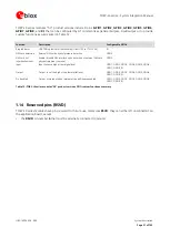
custom functions as summarized in Table 12.
Function
Description
Configurable GPIOs
Ring Indicator
UART0 Ring Indicator functionality (Circuit 125 in ITU-T V.24)
RI
SIM card detection
External SIM card physical presence detection
GPIO5
SIM card hot
insertion/removal
Enable / disable SIM interface upon detection of external SIM card
physical insertion / removal
GPIO5
Input
Input to sense high or low digital level
GPIO1, GPIO2, GPIO3, GPIO4, GPIO5, GPIO6,
GPIO7, GPIO8, RI
Output
Output to set the high or the low digital level
GPIO1, GPIO2, GPIO3, GPIO4, GPIO5, GPIO6,
GPIO7, GPIO8, RI
Pin disabled
Output tri-stated with an internal active pull-down enabled
GPIO1, GPIO2, GPIO3, GPIO4, GPIO5, GPIO6,
GPIO7, GPIO8, RI
Table 12: TOBY-L4 series modules "50" product versions GPIO custom functions summary
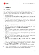
1.14
Reserved pins (RSVD)
TOBY-L4 series modules have pins reserved for future use, marked as
RSVD
: they can all be left unconnected on
the application board, except
the
RSVD
pin number
6
that must be externally connected to ground

