25
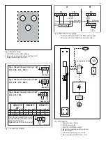
Fig. 7 Connections diagram
Fig. 8 Alternative wiring, lighting
A. Internal LED controlled from Elite control panel
B. Internal LED controlled from external switch
Don´t forget to earth (ground)!
Vergessen Sie nicht zu erden!
Glöm inte att jorda!
Nóubliez pas la mise à la terre!
kW
2,2
4,5
AWG
400-415 V
2N~
-
-
mm²
200-208 V~
230-240 V~
AWG
2.5
6
-
-
mm²
AWG
1.5
4
14
12
mm²
1.5 14
-
Amp
10
11
Amp
23
10
Amp
20
A
G
B C D
200-240 V~
1A
1A
1A
Type: Steam Shower Stella 2.2 kW
Type: Steam Shower Stella 4.5 kW
Type: Steam Shower Stella 4.5 kW
200 - 208 - 230 - 240 V~
200 - 208 - 230 - 240 V~
400 - 415 V 2N~
A
G
B C D
200-240 V~
A
G
B C D
400-415 V 2N~
L1L2
N
A1A2
1C
A3A4
G
AUX0
200-
240 V~
*
*
Max 10A
+ -
1E
3
12VDC
4 5
Transformer
B.
200-
240 V~
Inside Stella
Outside Stella
F1 F2
1B
P1 P2 N1 N2
+ -
1E
3
12VDC
4 5
Transformer
A.
Inside Stella
Outside Stella
200-
240 V~
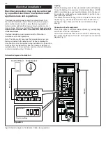
Fig. 9 Connection
1. Steam column, Stella
2. Main power switch
3. Electrical distribution board
4. Residual current device max. 30mA
5. Power switch
6. 12VDC Transformer, min. 20 W
7. Extra equipment (AUX) max. 10 A
ON
OFF
ON
12VDc
20W
OFF
1.
2.
3.
5.
6.
7.
4.
<30 mA
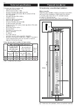
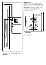
Fig. 6 Electrical wiring
1. 12VDC for built-in LED lighting
2. Any extra equipment such as lighting, AUX
3. Main power supply to Stella
1.
2.
3.


