background image

24

Electrical installation

Lighting

The Stella steam generator has pre-installed built-in LED lighting. 

To use the lighting, it is necessary to install a transformer (12VDC 

20W) in a suitable place and install trunking up to the Stella unit. 

It can either be controlled by an external switch or via the control 

panel (see Figs. 8 and 9).

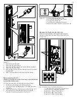
To facilitate the internal routing of the 12 V cable to terminal block 

1E (see Fig. 9 ), use the included 10 mm flex tube and route it 

as shown in Fig.5. Make sure that the routed cables are long 

enough.

Connection of extra equipment

There is the option to connect extra equipment, e.g. extra lighting, 

and control it from the control panel. 

The number of functions that can be connected is determined by 

the number of AUX inputs. There is 1 AUX input. See connections 

diagram

 (Fig. 7)

.

Electrical connection may only be carried out 

by a qualified electrician in accordance with 

applicable laws and regulations.

The steam generator power supply line comes directly from 

the electrical distribution board. This line should be equipped 

with a multi-pole main switch to allow the steam generator to 

be temporarily switched off during servicing. A residual current 

device of max. 30mA must be fitted. 

The circuit breaker may be 

switched off no sooner than 90 minutes after completed use 

of the steamroom.

The fixed installation must include a switch-off function in 

accordance with valid regulations.
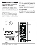
Note: The Elite control panel and the temperature sensor are 

factory-connected to the relay board. The box containing the 

relay board must not be opened during installation. Only open the 

box to perform troubleshooting. See the 

Schematic diagram of 

installation (Fig. 9) 

for connections, and also refer to the 

Modular 

contactor description (Fig. 10, table 2).

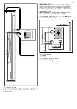
Fig.5 Schematic diagram of installation, Stella steam generator

1A

1B

1C

12V Aux

1E

Control Panel Temp Sensor

Pos. 6-9

On

Off

1

2

Dipswitch

1

2

6

7

8

9

3

4

5

CTS

3

4

5

6

Steam private

Factory settings

500 mm

Schematic diagram of installation

Содержание STELLA

Страница 1: ...ING ENGLISH INSTALLATION USER GUIDE DEUTSCH INSTALLATIONS BEDIENUNGSAN LEITUNG FRANÇAIS INSTALLATION MODE D EMPLOI РУССКИЙ РУКОВОДСТВО ПО УСТАНОВКЕ ЭКСПЛУАТАЦИИ POLSKI INSTRUKCJA INSTALACJI OBSŁUGI NEDERLANDS INSTALLATIE GEBRUIKERSHAND LEIDING SUOMI ASENNUS KÄYTTÖOHJEET IPX5 ...

Страница 2: ... generator 21 Technical specifications 22 Correct power output in relation to room volume 22 Pipework installation 22 Water connection 22 Electrical installation 24 Schematic diagram of installation 24 Lighting 24 Connection of extra equipment 24 Modular contactor description 26 Spare parts list 27 User Guide 28 Elite control panel 28 Main power switch 28 Automatic emptying during operation 28 Des...
Страница 3: ...zards involved Do not allow children to play with the appliance Children must not clean or perform maintenance on the appliance without supervision This appliance is not intended for use by persons including children with reduced physical sensory or mental capabilities or who lack knowledge and experience of the appliance unless they have been given appropriate instruction by a person responsible ...

Страница 4: ...o a ventilation duct that conducts the air outdoors An existing duct could be utilised The ventilation duct must be completely sealed and made of a material that tolerates high air humidity Water pockets where condensed water can collect and cause blockages must not be present If the ventilation duct is required to have a water pocket a water trap must be installed to drain condensate into the dra...

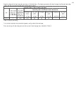
Страница 5: ...uct must be installed and used so as to maintain a minimum distance of 20 cm from the user Correct power output in relation to room volume kW Max recom steamroom volume m Steam prodn kg h Toughened glass lightweight wall Elysée Excellent room etc Heavyweight wall made of concrete stone tiles etc with venti lation without venti lation with venti lation without ventilation 2 2 2 5 1 5 3 4 5 4 5 5 2 ...

Страница 6: ...g water supply is connected to the steam generator the piping system must be flushed through Flushing prevents metal particles and other impurities entering the steam generator system from the piping IMPORTANT The incoming water pressure must be between 1 and 5 bar min 100kPa and max 500kPa It is an advantage to install a shut off valve in the water supply line to facilitate repairs servicing 1435...

Страница 7: ...plicable laws and regulations The steam generator power supply line comes directly from the electrical distribution board This line should be equipped with a multi pole main switch to allow the steam generator to be temporarily switched off during servicing A residual current device of max 30mA must be fitted The circuit breaker may be switched off no sooner than 90 minutes after completed use of ...

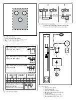
Страница 8: ...hower Stella 4 5 kW 200 208 230 240 V 200 208 230 240 V 400 415 V 2N A G B C D 200 240 V A G B C D 400 415 V 2N L1L2 N A1A2 1C A3A4 G AUX0 200 240 V Max 10A 1E 3 12VDC 4 5 Transformer B 200 240 V Inside Stella Outside Stella F1 F2 1B P1 P2 N1 N2 1E 3 12VDC 4 5 Transformer A Inside Stella Outside Stella 200 240 V Fig 9 Connection 1 Steam column Stella 2 Main power switch 3 Electrical distribution b...

Страница 9: ...WG24 2 Modular jack RJ10 connected to relay board and control panel 3 Relay board high Pos 6 9 white connectors Pos Unit Use pin Comment Pin1 Pin 2 Pin 3 Pin 4 1 NTC Temp sensor 2 3 Model NTC 10kΩ Not use NTC 10kΩ NTC 10kΩ Not use 2 EXT SWITCH Not used for Stella steam generator 3 DOOR SWITCH Not used for Stella steam generator 4 SEC NTC Not used for Stella steam generator 5 ADD ON Not used for St...

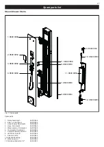
Страница 10: ...Relay board High 9600 0068 2 Elite control panel 9600 0954 3 Hand shower Dornbracht 9600 0962 4 Hose Dornbracht 9600 0960 5 Water selector Dornbracht 9600 0958 6 Thermostat Dornbracht 9600 0956 7 Complete steam generator 9600 0966 8 LED strip 2 pack 9600 0964 9 Solenoid valve 9600 0063 10 Electrode bushing 9600 0950 11 Water reservoir 9600 0952 12 Motorised ball valve 1 2 9600 0283 Fig 11 Spare pa...

Страница 11: ...epends on the water s original dH level and on the descaler used Other minerals that may cause deposits to develop will still remain in the water To test the degree of hardness follow the EASY TEST instructions provided and then comply with the recommendations in table 3 Note If the steam generator is only used to a limited extent e g for a short time about once a week In such cases the steam gene...

Страница 12: ...s Item No 90903000 Tylö liquid descaling agent ml Item No 90903002 Operating hours at different water hardnesses Softened water 0 1 dH Very soft water 0 3 dH Soft water 4 7 dH Medium hard water 7 14 dH Hard water 14 21 dH Very hard water 21 dH 2 2 4 5 1 250 100 60 50 40 Table 3 Rules for descaling It is not recommended to operate the appliance using water of this hardness Take care during the desc...

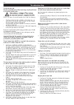
Страница 13: ...ol panel will switch off Remedy Reset the temperature cut out See the Temperature cut out section 8 Fault cause Internal circuit board fault or control panel fault Remedy Replace the faulty component Water flows out of the steam nozzle unevenly or water flows out with reduced pressure mixed with steam Info It is normal for a little water to periodically drip from the steam nozzle 1 Fault cause Bui...

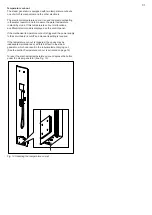
Страница 14: ...de is displayed on the control panel If the mechanical temperature cut out is triggered the power supply to the circuit board is cut off and manual resetting is required If the temperature cut out is triggered the cause may be inadequate maintenance or an internal fault in the steam generator which can result in the tubular element drying out See the section Temperature cut out is activated on pag...

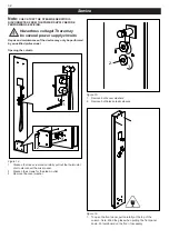
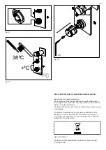
Страница 15: ...r supply circuits Service Figure 14 1 Slacken the lock screw and carefully pull out the thermostat dial to disconnect the mixer panel 2 Slacken the screws for the steam outlet 3 Remove the cover washer Figure 15 1 Remove both cover washers 2 Remove both black plastic sleeves Figure 16 1 To open the front panel pull carefully at the top of the column Note Mind the glass when putting the front panel...

Страница 16: ...3 Open the front cover on the column as shown in Figs 14 17 4 Pull out the knob on the ball valve and turn it until the indicator shows the open position See Fig 18 Figure 18 1 Vertical line indicates open valve 2 Horizontal line indicates closed valve 3 Pull the knob straight out 4 Turn the knob to open close the valve 5 Depress the knob to return to automatic mode 1 2 3 4 5 Replacement of faulty...

Страница 17: ...IMPORTANT The electrode pins must not have fat deposits or other deposits on them The electrode pins must not touch each other This could affect the control of the steam generator water level Connect the electrodes as follows see Fig 20 1 Black electrode High Level Connector pin H on circuit board 2 White electrode GND Connector pin GND on circuit board 3 Red electrode Mid Level Connector pin M on...

Страница 18: ...hen it is no longer in use Take it to a recycling station for electrical and electronic equipment instead For further information refer to the symbol on the product manual or packaging The different materials may be recycled as specified on their labelling You can help protect the environment by recycling or reusing the spent appliances or the materials in them Take the product to a recycling cent...

Страница 19: ...ктеристики 73 Правильная выходная мощность в зависимости от объема помещения 73 Установка системы трубопроводов 73 Подключение воды 73 Электромонтаж 75 Схема установки 75 Освещение 75 Подключение дополнительного оборудования 75 Описание модульного контактора 77 Перечень запасных частей 78 Руководство пользователя 79 Панель управления Elite 79 Выключатель сетевого питания 79 Автоматическое опорожне...

Страница 20: ...ать с прибором Дети не должны чистить или обслуживать прибор без присмотра Данное устройство не предназначено для использования лицами включая детей с ограниченными физическими сенсорными или умственными способностями либо не имеющими знаний и опыта работы с устройством если они не получили соответствующих инструкций от лица ответственного за их безопасность Они могут использовать прибор под присм...

Страница 21: ...ое вентиляционное отверстие должно быть соединено с вентиляционным каналом для вывода воздуха за пределы помещения Можно использовать уже имеющийся вентиляционный канал Вентиляционный канал должен быть полностью герметичен и выполнен из материала способного выдерживать высокую влажность воздуха В нем не должно быть водяных карманов в которых может накапливаться водяной конденсат вызывая перекрытие...

Страница 22: ...м модулем WiFi 2412 2462 МГц 20 дБм Изделие необходимо устанавливать и использовать на расстоянии не менее 20 см от пользователя Правильная выходная мощность в зависимости от объема помещения кВт Макс реком объем парной м Генерация пара кг ч Легкая стена из закаленного стекла комната Elysée Excellent и т д Тяжелая стена облицованная плиткой бетонная каменная и т д с венти ляцией без венти ляции с ...

Страница 23: ...ением поступающей воды к парогенератору надлежит выполнить промывку системы трубопроводов Такая промывка предотвращает попадание металлических частиц и других посторонних объектов из трубопровода в парогенератор ВНИМАНИЕ Давление поступающей воды должно находиться в диапазоне от 1 до 5 бар от 100 кПа до 500 кПа Установка запорного клапана на линии подачи воды станет преимуществом при ремонт обслуж...

Страница 24: ...рованным электриком в соответствии с применимыми законами и правилами Линия подачи питания идет непосредственно от электрораспределительного щита Эта линия должна быть оборудована многополюсным выключателем сетевого питания чтобы можно было временно отключить парогенератор во время обслуживания Необходимо установить устройство дифференциальной защиты макс 30 мА Выключать питание посредством размык...

Страница 25: ...tella 4 5 kW 200 208 230 240 V 200 208 230 240 V 400 415 V 2N A G B C D 200 240 V A G B C D 400 415 V 2N L1L2 N A1A2 1C A3A4 G AUX0 200 240 V Max 10A 1E 3 12VDC 4 5 Transformer B 200 240 V Inside Stella Outside Stella F1 F2 1B P1 P2 N1 N2 1E 3 12VDC 4 5 Transformer A Inside Stella Outside Stella 200 240 V Рис 9 Соединения 1 Паровая установка Stella 2 Выключатель сетевого питания 3 Электрораспредел...

Страница 26: ... и панели управления 3 Релейная плата поз 6 9 белые разъемы Поз Элемент Используемые контакты Примечание Контакт 1 Контакт 2 Контакт 3 Контакт 4 1 NTC Темп датчик 2 3 Модель NTC 10 кОм Не используется NTC 10 кОм NTC 10 кОм Не использ уется 2 ВНЕШНИЙ ВЫКЛЮЧАТЕЛЬ Не используется для парогенератора Stella 3 ДВЕРНОЙ ПЕРЕКЛЮЧАТЕЛЬ Не используется для парогенератора Stella 4 SEC NTC Не используется для ...

Страница 27: ...0 0068 2 Панель управления Elite 9600 0954 3 Лейка для душа Dornbracht 9600 0962 4 Шланг Dornbracht 9600 0960 5 Селектор воды Dornbracht 9600 0958 6 Термостат Dornbracht 9600 0956 7 Полный парогенератор 9600 0966 8 Светодиодная лента 2 шт 9600 0964 9 Электромагнитный клапан 9600 0063 10 Электродный переходник 9600 0950 11 Резервуар для воды 9600 0952 12 Шаровой клапан с электроприводом 1 2 дюйма 9...

Страница 28: ...вня dH в воде и от используемого средства для удаления накипи Другие минералы которые могут вызвать образование отложений все равно останутся в воде Чтобы определить уровень жесткости воды следуйте прилагаемым инструкциям по проведению теста EASY TEST а затем следуйте рекомендациям в соответствии с таблицей 3 Примечание Если парогенератор используется только в ограниченном объеме например в течени...

Страница 29: ...кул 90903000 Жидкое средство для удаления накипи Tylö мл артикул 90903002 Часы работы при различных уровнях жесткости воды Смягченная вода 0 1 dH Очень мягкая вода 0 3 dH Мягкая вода 4 7 dH Вода средней жесткости 7 14 dH Жесткая вода 14 21 dH Очень жесткая вода 21 dH 2 2 4 5 1 250 100 60 50 40 Таблица 3 Инструкции по удалению накипи Не рекомендуется эксплуатировать изделие с водой такой жесткости ...

Страница 30: ...едохранитель 4 Причина неполадки Неисправен сломан трубчатый элемент парогенератора Способ устранения Замените трубчатый элемент 5 Причина неполадки Начатый сеанс паровой бани был отключен время сеанса закончилось сеанс отключен вручную или сгенерирован код ошибки Способ устранения Проверьте статус панели управления начните новый сеанс паровой бани См инструкции по эксплуатации панели управления 6...

Страница 31: ...ды индикации переполнения бака не работают Сначала прочтите список кодов ошибок в инструкции пользователя панели управления Elite Также см раздел Электроды уровень воды в этих инструкциях 1 Причина неполадки Запорный клапан если он есть в линии подачи воды к парогенератору не закрыт Способ устранения Откройте запорный клапан 2 Причина неполадки Электроды не определяют уровень воды Способ устранени...

Страница 32: ...лько Обслуживание Рис 14 1 Ослабьте стопорный винт и осторожно потяните ручку термостата чтобы отсоединить панель смесителя 2 Ослабьте винты выхода пара 3 Снимите шайбу крышки Рис 15 1 Снимите обе шайбы крышки 2 Снимите обе черных пластиковых втулки Рис 16 1 Чтобы открыть переднюю панель осторожно потяните за верхнюю часть установки Примечание Будьте аккуратны со стеклом когда кладете переднюю пан...

Страница 33: ...ановке как показано на рис 14 17 4 Вытяните ручку на шаровом клапане и поверните ее пока индикатор не покажет открытое положение См рис 18 Рис 18 1 Вертикальная линия указывает на открытый клапан 2 Горизонтальная линия указывает на закрытый клапан 3 Вытяните ручку прямо 4 Поверните ручку чтобы открыть закрыть клапан 5 Нажмите ручку чтобы вернуться в автоматический режим 1 2 3 4 5 Замена неисправно...

Страница 34: ...ектродов не должно быть жировых или других отложений Штифты электродов не должны касаться друг друга Это может повлиять на контроль уровня воды в парогенераторе Подключите электроды следующим образом см рис 20 1 Черный электрод высокий уровень контакт H на печатной плате 2 Белый электрод земля контакт GND на печатной плате 3 Красный электрод средний уровень контакт M на печатной плате Электроды ур...

Страница 35: ...для электрического и электронного оборудования Дополнительная информация содержится на нанесенном на изделии символе а также на упаковке и в руководстве Для получения информации о ближайшем центре переработки обратитесь в местные полномочные органы Путем переработки и повторного использования изделий срок службы которых истек а также содержащихся в них материалов вы можете посодействовать делу защ...

Отзывы: