background image

11

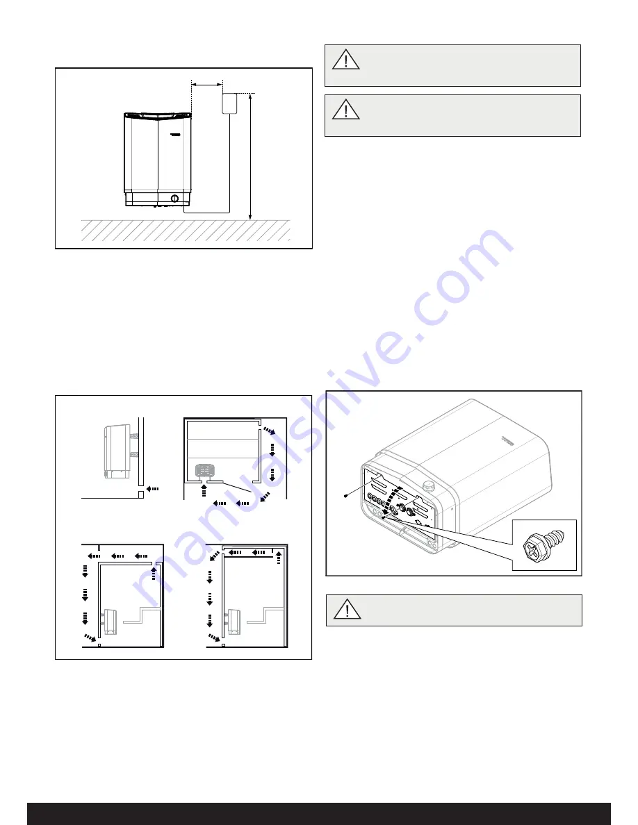
Positioning the inlet vent

Install the inlet vent straight through the wall under the centreline 
of the heater.
Vent size for a family sauna approx. 125 cm².
The air circulation from the door must concord with the hot air 
circulation from the heater.

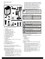
Figure 7: Positioning the air intake and exhaust vents

1.  Inlet vent position.
2.  Outlet vent position through the sauna wall.
3.  Outlet vent position through the cavity.
4.  Outlet vent position via duct.

Positioning the outlet vent

Position the outlet vent
• 

at the maximum possible distance from the air intake vent, 
e.g. diagonally (see Figure 7).

• 

high on the wall or in the ceiling (see Figure 7).

• 

so that it vents into the space that the door and air intake 
vent open into.

The outlet vent must have the same area as the inlet vent.
Ensure that the outlet vent is open.
Mechanical ventilation is not recommended due to the risk of poor 
air exchange, which can negatively aff ect the heater temperature 
cut-out.

1

2

3

4

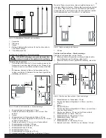
Figure 8: Opening/closing the cover

Connect the heater using standard wiring (Fk or EKK) approved 
for fi xed installation.
Any single wires (Fk) must be protected in electrical conduits (VP) 
to the heater.

3.

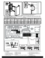
  Connect the electrical cable (1) to the terminal (2) (see Figure 

9) according to the wiring diagram (see the Connection/wiring 
diagram section, page 11).

INSTALLATION

Sauna heater installation

It is easiest to prepare for installation with the heater lying down.
To install the heater:

1. 

Lay the heater down with the front facing upwards.

2. 

Undo the screws and open the cover (see Figure 8).

DANGER! The air exhaust vent must not lead out-
doors. This could cause the ventilation direction 
to be reversed, which may negatively a

 ect the 

heater temperature cut-out.

DANGER! Any gap above the sauna ceiling 
should not be sealed without leaving at least one 
vent hole on the same wall as the sauna door!

WARNING! Always check that the heater is con-
nected to the correct main/phase voltage!

Positioning the control panel

The control panel must be correctly positioned with regard to
safety distances.

Figure 6: Safety distance, control panel

1.  Heater
2.  Control panel
3.  Max. 900 mm
4.  Min. 300 mm

2

4

3

1

Содержание Sense Pure

Страница 1: ...900 5190 SVENSKA INSTALLATIONSANVISNING ENGLISH INSTALLATION GUIDE DEUTSCH INSTALLATIONSANLEITUNG FRANÇAIS NOTICE D INSTALLATION РУССКИЙ ИНСТРУКЦИИ ПО УСТАНОВКЕ POLSKI INSTRUKCJA INSTALACJI NEDERLANDS INSTALLATIEHANDLEIDING A ...

Страница 2: ...ation 23 Conception de l installation 23 INSTALLATION 25 Installation du poêle de sauna 25 SCHÉMA DE RACCORDEMENT BRANCHEMENT 27 Description du câblage prises modulaires 28 AUTOCONTRÔLE DE L INSTALLATION 28 РУССКИЙ СОДЕРЖАНИЕ ПЕРЕД УСТАНОВКОЙ 30 Компоненты 30 Требования к установке 30 Инструменты для установки 30 План установки 30 УСТАНОВКА 32 Установка каменки 32 ПОДКЛЮЧЕНИЕ СХЕМА СОЕДИНЕНИЙ 34 О...

Страница 3: ...estande för personer med svag hälsa Rådgör med läkare Doftessenser etc kan innebära risk för antändning om de hälls outspädda på stenmagasinet Övertäckning av bastuaggregatet medför brandfara Om man häller vatten i luftfuktaren efter att den är upphettad finns det en stor risk att kokande vatten skvätter ut mot de badande Det är inte lämpligt att stå framför eller sitta på laven framför aggregat o...

Страница 4: ...acering se Avsnittet Aggregatets placering normalmontage sidan 2 Planera manöverpanelens placering se medföljande anvis ning för manöverpanel för tillåten placering Planera sensorns placering se Fig 3 sidan 2 samt Fig 5 sidan 2 Placera inluftsventilen se Avsnittet Inluftsventilens placering sidan 3 Placera utluftsventilen se Avsnittet Utluftsventilens placering sidan 3 Planera elinstallationen se ...

Страница 5: ...sensorn placeras i taket med avstånd från aggregatet enligt Fig 4 1 4 8 11 10 12 2 6 5 9 7 3 3 Fig 3 Placering av bastuaggregatet normalmontage 1 Minsta avstånd till sidovägg 110 mm 2 Sensorns placering alt 1 300 mm från aggregat 3 Sensorn 4 Minsta avstånd bakre vägg med ben 95 mm 5 Sensorns placering alt 2 300 mm från aggregatets front 6 Sensorns placering 150 mm från tak 7 Minsta avstånd till ta...

Страница 6: ...inluftsventilen Tillse att utluftsventilen är öppen Mekaniskt ventilation rekommenderas ej p g a risk för felaktig luftväxling som kan påverka aggregatets temperaturskydd nega tivt 1 2 3 4 Fig 8 Öppna stänga luckan Aggregatet ansluts med vanlig standardledning Fk eller EKK godkänd för fast installation Eventuell enkelledare Fk skyddas i elrör VP fram till aggrega tet 3 Anslut elkabeln 1 i plint 2 ...

Страница 7: ...olerna på aggregatet 9 Placera konsolskruvarna enligt måttsättning se Fig 11 2 4 3 1 4 Dra kablar för manöverpanel och temperatursensor genom kabelgenomföringarna 3 Anslut manöverpanelens kabel 4 i en av de fyra RS485 kontakterna position 5 8 5 se Fig 9 enligt kopplingsschema se Avsnittet Anslut ning kopplingsschema sidan 5 5 Anslut sensorns kabel 6 till NTC kontakten på kretskortet position 1 5 s...

Страница 8: ...P4C RJ10 4P4C Control panel Pure max 100m B B 6 6 8 0 kW 200 240 V 1N 2 6 6 8 0 10 5 kW 200 230 V 3 6 6 8 0 10 5 kW 400 415 V 3N Max 100W 0 5A Ovanliga spänningar fas tal Vid inkoppling till spänningar eller fas tal som inte anges i kopp lingsschema Fig 17 kontakta Tylö kundservice Fig 15 Montering av sensorn Fig 16 Täta eventuella hål ANSLUTNING KOPPLINGSSCHEMA TAB 400 415 V 3N 3 C 200 208 V 3 B ...

Страница 9: ...eler 6 RS485 manöverpaneler 7 RS485 manöverpaneler 8 RS485 manöverpaneler 9 Modularplugg 10 Modularkontakt Tabell 3 Inkoppling av komponenter i modularkontakter max kabelarea till RJ10 0 90 mm 0 20 mm AWG24 Inkoppling av Pos Pin Anmärkning Tempsensor 10kohm 1 2 3 Skall vara av modell NTC Kan även kopplas in på Pos 4 Externbrytare utan ledindikering 2 3 4 Både konstant eller impulsslutning fungerar...

Страница 10: ...e a fire Do not pour water into the fragrance holder once it has been heated up as this can cause boiling water to splash on the sauna occupants Do not stand or sit in front of the heater while water is being poured into the fragrance holder as hot water can spray out suddenly If the stone compartment fills up with gravel and small stones the tubular element can be damaged as a result of overheati...

Страница 11: ...sauna heater positioning see the Heater positioning normal installation section page 8 Plan the control panel positioning see the attached instruc tions for the control panel for allowable positioning Plan the sensor positioning see Figure 3 page 8 and Figure 5 page 8 Position the air intake vent see the Air intake vent positioning section page 9 Position the air exhaust vent see the Air exhaust v...

Страница 12: ...stalled in the ceiling at a distance from the heater according to Figure 4 1 4 8 11 10 12 2 6 5 9 7 3 3 Figure 3 Positioning the heater normal installation 1 Minimum distance from side wall 110 mm 2 Sensor position alt 1 300 mm from heater 3 Sensor 4 Minimum distance from back wall with legs 95 mm 5 Sensor position alt 2 300 mm from heater front 6 Sensor position 150 mm from ceiling 7 Minimum dist...

Страница 13: ...Opening closing the cover Connect the heater using standard wiring Fk or EKK approved for fixed installation Any single wires Fk must be protected in electrical conduits VP to the heater 3 Connect the electrical cable 1 to the terminal 2 see Figure 9 according to the wiring diagram see the Connection wiring diagram section page 11 INSTALLATION Sauna heater installation It is easiest to prepare for ...

Страница 14: ... the heater 9 Position the bracket screws according to the specified dimen sioning see Fig 11 2 4 3 1 4 Run the cables for the control panel and the temperature sensor through the cable grommets 3 Connect the control panel cable 4 to one of the four RS485 contacts positions 5 8 see Figure 9 according to the wiring diagram see the Connection wiring diagram section 5 Connect the sensor cable 6 to the...

Страница 15: ...4P4C RJ10 4P4C Control panel Pure max 100m B B 6 6 8 0 kW 200 240 V 1N 2 6 6 8 0 10 5 kW 200 230 V 3 6 6 8 0 10 5 kW 400 415 V 3N Max 100W 0 5A Unusual voltages numbers of phases Contact Tylö Customer Service before connecting to voltages or num bers of phases that are not listed in the wiring diagram Figure 17 Figure 15 Installing the sensor Figure 16 Seal any holes CONNECTION WIRING DIAGRAM TAB ...

Страница 16: ...TC Sensor option 5 RS485 control panels 6 RS485 control panels 7 RS485 control panels 8 RS485 control panels 9 Modular plug 10 Modular contact Table 3 Connecting components in modular contacts maximum cable area for RJ10 0 90 mm 0 20 mm AWG24 Connection of Pos Pin Comment Temp sensor 10kohm 1 2 3 Must be NTC model May also be connected at Position 4 External switch with no wire indicator 2 3 4 Bot...

Страница 17: ...en der Heizung kann einen Brand verursachen Schütten Sie kein Wasser in den Duftkonzentratbehälter sobald sich dieser erwärmt hat da andernfalls möglicherweise kochendes Wasser auf die Saunainsassen spritzt Stellen oder setzen Sie sich nicht vor die Heizung während Wasser in den Duftkonzentratbehälter geschüttet wird da plötzlich heißes Wasser heraussprühen kann Wenn sich Kies und Steinchen in der...

Страница 18: ...chnitt Position des Ofens Normalmontage Seite 14 Planen Sie die Position der Steuerung zur zulässigen Posi tion siehe beigefügte Anleitung für die Steuerung Planen Sie die Position des Sensors siehe Abb 3 Seite 14 sowie Abb 5 Seite 14 Finden Sie die korrekte Position für das Zuluftventil siehe Abschnitt Position des Zuluftventils Seite 15 Finden Sie die korrekte Position für das Abluftventil siehe...

Страница 19: ... der Sensor an der Decke angebracht werden Der Mindestabstand vom Ofen ist Abb 4 zu entnehmen 1 4 8 11 10 12 2 6 5 9 7 3 3 Abb 3 Position des Saunaofens Normalmontage 1 Mindestabstand zur Seitenwand 110 mm 2 Position des Sensors Möglichkeit 1 300 mm vom Ofen entfernt 3 Sensor 4 Mindestabstand zur Rückwand mit Füßen 95 mm 5 Position des Sensors Möglichkeit 2 300 mm von der Vorder seite des Ofens en...

Страница 20: ...stoffaderleitung oder Kunststoffschlauchleitung angeschlossen die für Festanschlüsse zugelassen sind Eventuelle Kunststoffaderleitungen werden in Kabelrohren ge schützt zum Ofen verlegt 3 Schließen Sie das Stromkabel 1 gemäß dem Schaltplan siehe Abschnitt Anschluss Schaltplan Seite 17 an die Klemme 2 an siehe Abb 9 INSTALLATION Installation des Saunaofens Die Installation lässt sich am einfachsten vo...

Страница 21: ... rungen nacheinander am Ofen montiert Abb 10 Montage der Halterungen am Ofen 9 Positionieren Sie die Schrauben der Halterung siehe Abb 11 2 4 3 1 4 Ziehen Sie die Kabel für die Steuerung und den Tempera tursensor durch die Kabeldurchführungen 3 Schließen Sie das Kabel 4 der Steuerung gemäß dem Schaltplan siehe Abschnitt Anschluss Schaltplan Seite 17 an eine der vier RS485 Buchsen Position 5 8 5 an...

Страница 22: ...nel Pure max 100m B B 6 6 8 0 kW 200 240 V 1N 2 6 6 8 0 10 5 kW 200 230 V 3 6 6 8 0 10 5 kW 400 415 V 3N Max 100W 0 5A Anomale Spannungen Phasenzahlen Bei Anschluss an Spannungen oder Phasen die nicht im Schalt plan Abb 17 verzeichnet sind wenden Sie sich an den Tylö Kun denservice Abb 15 Montage des Sensors Abb 16 Abdichten von ggf gebohrten Löchern ANSCHLUSSDIAGRAMM SCHALTPLAN TAB 400 415 V 3N 3...

Страница 23: ...en 7 RS485 Steuerungen 8 RS485 Steuerungen 9 Modularstecker 10 Modularbuchse Tabelle 3 Anschluss von Komponenten an Modularbuchsen maximale Kabelfläche für RJ10 0 90 mm 0 20 mm AWG24 Anschluss von Position PIN Anmerkung Temperatursensor 10 kOhm 1 2 3 Muss vom Typ NTC sein Der Anschluss ist auch möglich an Position 4 Externschalter ohne Adermarkierung 2 3 4 Funktioniert sowohl mit Dauer als auch mi...

Страница 24: ...mer si le liquide est versé sur le réservoir à pierres Le fait de recouvrir le poêle risque de causer un incendie Ne versez pas d eau dans l humidificateur une fois qu il est chaud car de l eau bouillante risquerait d éclabousser les occupants du sauna Il est déconseillé de se tenir debout ou assis sur la banquette de vant le poêle lorsque de l eau est versée dans le récipient à parfum en raison d...

Страница 25: ...tion Emplace ment du poêle montage normal page 20 Planifier l emplacement du panneau de commande voir les instructions jointes pour le choix de l emplacement du pan neau de commande Planifier l emplacement des capteurs voir la figure 3 page 20 et la figure 5 page 20 Prévoir l emplacement de la bouche d entrée d air voir la section Emplacement de la bouche d entrée d air page 21 Prévoir l emplacement d...

Страница 26: ...à la figure 4 1 4 8 11 10 12 2 6 5 9 7 3 3 Fig 3 Emplacement du poêle montage normal 1 Distance minimum par rapport aux cloisons latérales 110 mm 2 Emplacement du capteur option 1 à 300 mm du poêle 3 Capteur 4 Distance minimum à la paroi de fond pieds inclus 95 mm 5 Emplacement du capteur option 2 à 300 mm de la façade du poêle 6 Emplacement du capteur à 150 mm par rapport au plafond 7 Distance min...

Страница 27: ...otection thermique du poêle 1 2 3 4 Fig 8 Ouverture fermeture du volet Utiliser un câble standard norme FK ou EKK homologué pour installation fixe Le cas échéant les fils électriques simples FK seront protégés du poêle par des gaines PV 3 Raccorder le câble électrique 1 au rack 2 voir la figure 9 selon schéma de raccordement voir la section Schéma de raccordement branchement page 23 INSTALLATION Inst...

Страница 28: ...poêle 9 Installer les vis pour support d après les cotes voir la figure 11 2 4 3 1 4 Acheminer les câbles du panneau de commande et du capteur de température à travers les passages de câble 3 Raccorder le câble du panneau de commande 4 à l un des quatre connect eurs RS485 positions 5 à 8 5 voir la figure 9 selon le schéma de raccordement voir la section Schéma de raccordement bran chement 5 Raccorde...

Страница 29: ...C RJ10 4P4C RJ10 4P4C Control panel Pure max 100m B B 6 6 8 0 kW 200 240 V 1N 2 6 6 8 0 10 5 kW 200 230 V 3 6 6 8 0 10 5 kW 400 415 V 3N Max 100W 0 5A Tensions nombre de phases inhabituels Pour le raccordement à des tensions ou un nombre de phases ne figurant pas sur le schéma de raccordement figure 17 contacter le service client Tylö Fig 15 Montage du capteur Fig 16 Boucher les orifices le cas éché...

Страница 30: ... Panneaux de commande RS485 8 Panneaux de commande RS485 9 Prise modulaire 10 Contact modulaire Tableau 3 Raccordement des composants des contacts modulaires section de câble max pour RJ10 0 90 mm 0 20 mm AWG24 Enclenchement hors tension Pos Rack Remarque Capteur de température 10 kohm 1 2 3 Doit être de type NTC Peut aussi se connecteur en Pos 4 Interrupteur extérieur sans diode 2 3 4 Versions à ...

Страница 31: ...продуктов непосредственно на камни такие вещества могут воспламениться Накрывание нагревателя может вызвать пожар Не наливайте воду в нагретый держатель для ароматизаторов так как это может привести к тому что кипящая вода выплеснется на лиц находящихся в сауне Не стойте и не сидите перед нагревателем во время наливания воды в держатель для ароматизаторов так как горячая вода может неожиданно выпл...

Страница 32: ...азмещение каменки нормальная установка страница 26 Спланировать размещение панели управления см прилагаемые инструкции для допустимого размещения панели управления Спланировать размещение датчика см рис 3 страница 26 а также рис 5 страница 26 Разместить впускной клапан см раздел Размещение впускного клапана страница 27 Разместить выпускной клапан см раздел Размещение выпускного клапана страница 27...

Страница 33: ...тройства согласно рис 4 1 4 8 11 10 12 2 6 5 9 7 3 3 Рисунок 3 Размещение каменки нормальная установка 1 Минимальное расстояние до боковой стены 110 мм 2 Размещение датчика вариант 1 300 мм от устройства 3 Датчик 4 Минимальное расстояние от задней стены с ножками 95 мм 5 Размещение датчика вариант 2 300 мм от переда устройства 6 Размещение датчика 150 мм от потолка 7 Минимальное расстояние до пото...

Страница 34: ... помощью обычного стандартного провода Fk или EKK предназначенного для быстрой установки Одножильный провод Fk если имеется защищён электрической трубкой VP до места соединения с устройством 3 Подключите провод 1 к соединению 2 см рис 9 согласно схеме соединений см раздел Подключение схема соединений страница 29 УСТАНОВКА Установка каменки Подготовку к установке можно упростить если разместить уст...

Страница 35: ...нок 10 Крепление кронштейнов на устройстве 9 Разместите винты кронштейнов согласно указанным размерам см рис 11 2 4 3 1 4 Протяните кабели к панели управления и датчику температуры через кабельные вводы 3 Подключите кабель панели управления 4 к одному из четырех контактов RS485 поз 5 8 5 см рис 9 в соответствии со схемой соединений см раздел Подключение схема соединений страница 29 5 Подключите ка...

Страница 36: ... 2 x 0 75 mm 2 RJ10 4P4C RJ10 4P4C RJ10 4P4C Control panel Pure max 100m B B 6 6 8 0 kW 200 240 V 1N 2 6 6 8 0 10 5 kW 200 230 V 3 6 6 8 0 10 5 kW 400 415 V 3N Max 100W 0 5A Необычные источники напряжения число фаз При подключении к источникам напряжения или при ином числе фаз не указанном в схеме соединений рис 17 свяжитесь с технической службой Tylö Рисунок 15 Установка датчика Рисунок 16 Уплотн...

Страница 37: ...8 RS485 панель управления 9 Модульный разъем 10 Модульный контакт Таблица 3 Подключение компонентов к модульным разъемам макс поперечное сечение кабеля для RJ10 0 90 мм 0 20 мм AWG24 Подключение Поз Вывод Примечание Температурный датчик 10 кОм 1 2 3 Должен быть модели NTC Может также быть подключен к поз 4 Внешний переключатель без LED индикатора 2 3 4 Работает как постоянное так и импульсное подк...

Страница 38: ...ednio na kamienie mogą się zapalić Przykrywanie pieca innymi przedmiotami może doprowadzić do pożaru Nie wlewaj wody do rozgrzanego zbiorniczka na esencje zapachowe ponieważ wrzątek mógłby wtedy po parzyć użytkowników sauny Podczas nalewania wody do zbiorniczka na esencje zapachowe nie stawaj ani nie siadaj przed piecem ponieważ w każdej chwili może z niego trysnąć gorąca woda Jeśli komora kamieni...

Страница 39: ...umiejscowienie panelu sterowania należy sprawdzić w załąc zonej instrukcji obsługi Zaplanować umiejscowienie czujnika patrz rys 3 strona 32 oraz rys 5 strona 32 Określić położenie wlotu powietrza patrz punkt Umiejs cowienie wlotu powietrza strona 33 Określić położenie wylotu powietrza patrz punkt Umiejs cowienie wylotu powietrza strona 33 Zaplanować instalację elektryczną patrz punkt Podłączanie s...

Страница 40: ... lub ze szkła hartowanego czujnik można umieścić na suficie tak by jego odległość od pieca była zgodna z podaną na rys 4 1 4 8 11 10 12 2 6 5 9 7 3 3 Rys 3 Umiejscowienie pieca do sauny montaż standardowy 1 Minimalny odstęp od ściany bocznej 110 mm 2 Umiejscowienie czujnika opcja 1 300 mm od pieca 3 Czujnik 4 Minimalny odstęp od ściany tylnej z nogami 95 mm 5 Umiejscowienie czujnika opcja 2 300 mm ...

Страница 41: ...rdowego przewodu LY lub YDY zatwierdzonego do instalacji stałej Ewentualny przewód pojedynczy LY należy zabezpieczyć rurą elektroinstalacyjną PVC na całej długości aż do pieca 3 Należy podłączyć kabel elektryczny 1 do zacisku 2 patrz rys 9 zgodnie ze schematem elektrycznym patrz punkt Podłączanie schemat elektryczny strona 35 INSTALACJA Instalacja pieca do sauny Przygotowania do instalacji najlepi...

Страница 42: ...ków na piecu 9 Śruby wsporników należy rozmieścić zgodnie z podanymi wymiarami patrz rys 11 2 4 3 1 4 Należy przeprowadzić kable panelu sterowania i czujnika tempera tury przez przepusty kablowe 3 Należy podłączyć kabel panelu sterowania 4 do jednego z czterech złączy RS485 poz 5 8 5 patrz rys 9 zgodnie ze schematem elektrycznym patrz punkt Podłączanie schemat elektryczny strona 35 5 Należy podłąc...

Страница 43: ...el Pure max 100m B B 6 6 8 0 kW 200 240 V 1N 2 6 6 8 0 10 5 kW 200 230 V 3 6 6 8 0 10 5 kW 400 415 V 3N Max 100W 0 5A Niestandardowe wartości napięcia liczby faz Przed podłączeniem pieca do napięcia o innej wartości lub do innej liczby faz niż podano w schemacie elektrycznym na rys 17 należy skontaktować się z Biurem Obsługi Klienta Tylö Rys 15 Montaż czujnika Rys 16 Uszczelnianie ewentualnych otw...

Страница 44: ...iwe zarówno ciągłe jak i impulsowe zamknięcie obwo du Wyłącznik zewnętrzny ze wskaź nikiem 2 2 3 4 12 V DC maks 40 mA Wyłącznik zewnętrzny Tylö nr artykułu 9090 8045 Przełącznik drzwiowy bez alarmu stanu drzwi 3 3 4 Model NO Normally Open Przełącznik drzwiowy Tylö nr artykułu 9090 8035 Przełącznik drzwiowy z alarmem stanu drzwi 3 2 3 4 12 V DC maks 40 mA Bezpiecznik termiczny z czujnikiem temperat...

Страница 45: ...achel wordt afgedekt kan er brand ontstaan Giet geen water in de geurhouder als het water al is opgewarmd omdat hierdoor kokend water kan ops patten waardoor mensen in de sauna brandwonden kunnen oplopen Ga niet voor de kachel zitten of sta an terwijl er water in de geurhouder wordt gegoten omdat hierdoor plotseling heet water kan opspatten Als er in het compartiment voor de stenen te veel gruis e...

Страница 46: ... Planning van de saunakachel normale montage pagina 38 De plaats van het bedieningspaneel plannen zie bijgevoeg de instructie voor toegestane plaatsen van het bedieningspa neel De plaats van de sensor plannen zie afb 3 op pagina 38 en afb 5 op pagina 38 De klep voor de inlaatlucht plaatsen zie Plaats van de klep voor de inlaatlucht pagina 39 De klep voor de uitgaande lucht plaatsen zie Plaats van ...

Страница 47: ... gehard glas kan de sensor in het plafond worden geplaatst met een afstand vanaf de kachel volgens afb 4 1 4 8 11 10 12 2 6 5 9 7 3 3 Afb 3 Plaatsing van de saunakachel normale montage 1 Kleinste afstand tot zijwand 110 mm 2 Plaatsing van de sensor alt 1 300 mm van de kachel 3 De sensor 4 Kleinste afstand tot achtermuur met bank 95 mm 5 Plaatsing van de sensor alt 2 300 mm van voorkant van de kach...

Страница 48: ...beveiliging van de kachel 1 2 3 4 Afb 8 Klepje openen sluiten De kachel wordt aangesloten met een gewone standaardkabel Fk of EKK goedgekeurd voor vaste installatie Eventueel wordt een kabel met één draad Fk beschermd door de elektrabuis VP tot aan de kachel 3 Sluit de elektrakabel 1 aan op de aansluitstrook 2 zie afb 9 volgens het koppelschema zie Aansluiting koppelsche ma pagina 41 INSTALLATIE I...

Страница 49: ...el monteren 9 Plaats de beugelschroeven volgens de aangegeven maten zie afb 11 2 4 3 1 Afb 9 De printplaat 1 Elektrakabel 2 Aansluitstrook voor aansluiten van elektrakabel 3 Kabeldoorvoering x6 4 Kabel van het bedieningspaneel 5 Modulaire stekkers voor aan sluiten van bedieningspaneel sensor enz 6 Kabel van de sensor 7 Eventuele verlichtingskabel 8 Aansluitstrook voor eventuele aansluiting van ver...

Страница 50: ...l panel Pure max 100m B B 6 6 8 0 kW 200 240 V 1N 2 6 6 8 0 10 5 kW 200 230 V 3 6 6 8 0 10 5 kW 400 415 V 3N Max 100W 0 5A Ongebruikelijke spanning fase Voor het aansluiten van spanningen of fases die niet worden aangegeven in het koppelschema van afb 17 neemt u contact op met de klantenservice van Tylö Afb 15 Montage van de sensor Afb 16 Dichten van eventuele gaten AANSLUIT EN BEDRADINGSSCHEMA TA...

Страница 51: ...edieningspanelen RS485 8 Bedieningspanelen RS485 9 Modulaire plug 10 Modulaire stekker Tabel 3 Aansluiten van componenten in modulaire contacten max kabelgrootte naar RJ10 0 90 mm 0 20 mm AWG24 Aansluiten van Pos Pen Opmerking Temperatuursensor 10 KOhm 1 2 3 Moet het model NTC hebben Kan ook worden aangesloten op Pos 4 Externe schakelaar zonder ledindi catie 2 3 4 Is mogelijk met zowel impuls als ...

Страница 52: ...50 431mm 600mm 206mm 375mm 262mm 262mm 262mm Måttuppgifter Dimensions Abmessungen Indication des dimensions Размеры Wymiarowanie Aangegeven maten ...

Отзывы: