9
PRIOR TO INSTALLATION
Parts
Check that the following parts are included in the packaging:
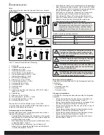
Figure 1: Sauna heater/control panel parts
1. Sauna heater
2. Herb bowl/air humidifi er
3. Brackets x 4
4. Bracket screws x 4
5. Warning sticker in ten languages
6. Lock screw B8x9.5 x 1
7. Connectors x 3
8. NTC Sensor, cable length 4 m
9. Clips TC (3-5) x 10 pieces
10. Plastic plugs 25x5 x 2 pieces
11. Screws RXS/A2 PHIL B6x25 x 2 pieces
12. Screw B4x6,5 x 1 piece
13. Sensor cover
14. Control panel
15. Cable between heater and control panel, RJ10 4P4C, cable
length 5 m x 1 pce
16. Cable tie
17. Clips C3x5 x 10 pcs
18. Modular plug 4, 4/4RJ10 x 2
19. Plastic plugs 25x5 x 3 pcs
20. Screws B6x25 x 3 pcs
Contact your dealer if anything is missing.
Control panel Pure is supplied with Sense MPE PURE. See sepa-
rate guide.
Installation requirements
To ensure safe use of the heater, check that the following criteria
are met:
•
Cable (EKK) or electrical ducting (Fk) for connecting the hea-
ter must be run on the outside of the heat insulation.
•
The cables must be run correctly (see the Connection/wiring
diagram section, page 11).
•
The fuse size (A) and the power cable size (mm²) must be
suitable for the heater (see the Connection/wiring diagram
section, page 11).
Installation tools
The following tools and materials are needed for installation and
connection:
• water level,
• adjustable spanner,
• electric drill,
• screwdrivers.
Installation planning
Before starting to install your sauna heater:
•
Plan the sauna heater positioning (see the Heater positioning
- normal installation section, page 8).
•
Plan the control panel positioning (see the attached instruc-
tions for the control panel for allowable positioning).
•
Plan the sensor positioning (see Figure 3, page 8 and Figure
5, page 8).
•
Position the air intake vent (see the Air intake vent positioning
section, page 9).
•
Position the air exhaust vent (see the Air exhaust vent positi-
oning section, page 9).
•
Plan the electrical installation (see the Connection/wiring
diagram section, page 11).
NOTE!
A brick wall without heat insulation increases
the warm-up time. Each square meter of plastered
ceiling or wall surface equals an additional 1.2–2 m³
of sauna volume.
3
2
1
8
7
17
4
5
6
15
16
14
18
19
9
20
10
11
12
13
DANGER! Poor ventilation or heater positioning
may lead to dry distillation, posing a
fi
re risk
under certain circumstances!
DANGER! Insu
ffi
cient insulation of the sauna
cabin may pose a
fi
re risk!
DANGER! Use of the wrong materials in the
sauna cabin, such as particle board, drywall, etc.,
may pose a
fi
re risk!
DANGER! The heater must be connected by a
quali
fi
ed electrician pursuant to applicable regu-
lations!
Table 1: Output and sauna volume
Output kW
Sauna volume min./max. m³
6,6
4-8
8
6-12
10,5
10-18
•
The sauna ventilation must comply with the instructions in
this manual (see the Air intake valve positioning section,
page 9, the Air exhaust valve positioning section, page 9).
•
The position of the sauna heater, control panel and sensors
must comply with the instructions in this manual.
•
The heater's output (kW) must be adapted to the sauna's vo-
lume (m³) (see Table 1, page 7). The minimum and maximum
volumes must not be exceeded.


