background image

7

B

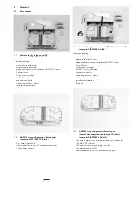
Loose tube ribbon cable

C

Central core cable

4.1.3

Kit content FIST-GR-CTB100 (loose tube ribbon)

Breakout screws

Breakout device cover + screws

Cable b screws

Mounting b w screws

2 cable clamps

Unraveling tool

2 strength member termin screws

4.1.4

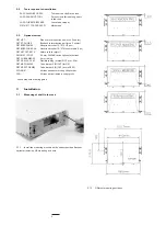
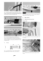
Choose a position in the side duct or on the cable termination

plate, close to the shelf. Mount the mounting bracket on that position

with the 2 screws. 

4.1.8

Choose a position in the side duct or on the cable termination

plate, close to the shelf. Mount the mounting bracket on that position

with the 2 screws. 

4.1.5

Loose tube ribbon cable.

4.1.6

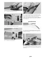
In case of loose tube cable: position the strength member at

the bottom. Bundle the loose tubes with tape. Secure the strength

member with the screws. Continue with installation from paragraph

4.1.15.

4.1.7

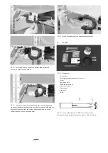
Kit content FIST-GR-CTB100CC (central core ribbon)

Breakout screws

Breakout cover screws

Cable b screws

Mounting b screws

2 cable clamps

Unraveling tool

2 strength member stops + screws

Содержание FIST-GPS2-J

Страница 1: ... 3 Installation of IFC cable on the tray 5 4 Installation of ribbon cable on the tray 6 Storage 7 Patching 8 Closing the shelf 9 Important steps Contents 1 Introduction Product function This shelf is a 19 mechanical enclosure for a physical fiber management system It is used for splicing and patching splicing primary coated fiber from loose tube cable or pigtails to fiber pigtails on a single elem...

Страница 2: ...nstallation of GPST 12 trays 2 pigtail horns 2 tray support wedges 4 GPST 12 trays prefibered cage nuts and bolts mounting brackets screws tie wraps adhesive foam installation instructions ID labels 2 General 2 1 Kit contents 2 1 4 GPST 12 tray configuration Patch splice Loose Tube and preconnecterised IFC cable example FIST GPST 12 AIA 2 Tray with 1x pigtail and 1x Splice Unit with splice holder ...

Страница 3: ... 45 mm 12 connector adaptors and pigtails per tray 3 GTU s Group Termination Unit per tray Always delivered in sets of 2 complementary pieces 2 1 7 Shelf with storage example FIST GPS2 J AAN T 1 unit incorporating metal chassis with drawer hingable metal front cover hinge and Velcro strap for installation of GPST 12 trays 2 pigtail horns 2 tray support wedges storage basket max 2 GPST 12 trays cag...

Страница 4: ... 2 3 Optional extras FIST UST Side cable termination unit max 2 cables FIST CT 2HU B 2 Back cable termination unit max 2 cables FIST MB2 2HU M Adaption bracket 19 ETSI 2 pcs FIST MB2 2HU M AS Adaption bracket 19 ETSI asymmetric 1 pc FISTV E7187 6316 Velcro rolls for pigtail SMOUV 1120 02 45 mm SMOUV fusion splice protections FIST TUBE 5MM 30 5 mm tubing FIST GS FLEX 12 50 Flexible tubing internal ...

Страница 5: ...cable back termination Spacing between adjacent units may vary depending on frame upright pitch and cable management products 3 2 Preparation of the shelf 3 3 Preparation of the trays 3 2 1 Pull the drawer to the fully open position and rotate the security lip 180 to prevent the drawer from moving back inside the unit 3 2 2 A trumpet is needed at the side where the pigtails are entering the shelf ...

Страница 6: ...x tube For central core cable fibers are guided into guiding tubes 5 mm who go direct into the shelf A Loose tube cable single fiber 4 1 1 Cut a flex tube to length according the cable position in the rack and remove the cable jacket according this length Make sure you have 2 m of loose tube inside the shelf 4 1 2 Make sure the flex tube is long enough so that the drawer slides easily in and out F...

Страница 7: ...h the 2 screws 4 1 8 Choose a position in the side duct or on the cable termination plate close to the shelf Mount the mounting bracket on that position with the 2 screws 4 1 5 Loose tube ribbon cable 4 1 6 In case of loose tube cable position the strength member at the bottom Bundle the loose tubes with tape Secure the strength member with the screws Continue with installation from paragraph 4 1 ...

Страница 8: ...tube divider FIST GPS2 TD 5MM can be mounted in the shelf Assemble the tube divider as shown Remove the Velcro strip from the shelf and mount it on the cover 4 1 10 Mount the cable bracket with 2 screws on the mounting bracket and place the breakout device on the cable bracket 4 1 11 Loosen the screw of the strength member stop Rotate the stop and position the strength members inside 4 1 12 Secure...

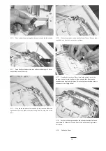
Страница 9: ...al practice 4 1 16 Slide the tool over the ribbons Bundle at the end using Teflon tape bundle in groups as you want to feed them through the tubes Remove the unraveling device 4 1 17 Mount the tube divider if needed on the metal tray Cut the tubes coming from the break out device to length Remove the tube divider to have better access to split out the ribbons 4 1 18 Insert the tubes in the connect...

Страница 10: ...p 2 tie wraps 1 tube holder bracket 4 2 Side cable termination directly on the shelf 4 2 1 The cable can be terminated on the shelf cable terminations are suited for max 2 cables cable retention with tie wraps the loose tubes are fed through a flexible tube to the shelf the strength member is attached to the plate A Loose tube cable 4 2 3 The picture shows left side mounting and cable coming from ...

Страница 11: ... platform Assure that tie wraps are well tensioned to avoid slippage of the tube and cut the excess length of the tie wraps Knobs of the tie wraps must be positioned at the FRONT of the metal hinge plate 4 2 8 Remove the cable jacket over approximately 2 2 m Wait to strip the loose tube to avoid fiber breakage Cut the strength member to length l max 60 mm l 4 2 9 Guide the identified loose tubes i...

Страница 12: ... tie wraps Note the correct orientation of the tie wraps Mount the cover on the flex tube holder 4 2 12 For cable coming from top use a reverse assembly 4 2 14 In case of IFC remove X 800 mm of outer jacket The recommended length of secondary fiber L 1250 1500 mm 4 2 13 Kit contents 1 metal plate 2 strength member connectors screws 1 drum 3 bolts and nuts 4 releasable tie wraps 1 edge protection 1...

Страница 13: ...ble coming from the left seen from the back for cable coming from right the reverse assembly is required X 80 mm 4 3 4 Apply 1 layer of foam tape around the flex tube at approximately 10 mm from the end This foam tape must be positioned underneath 1 of the tie wraps this tape prevents easy pull out of the flex tube X 80 mm 4 3 5 Fasten the flex tube before trays are inserted or remove trays at the...

Страница 14: ...rength member and loose buffer tubes Attach the cable with the releasable tie wraps on the outer jacket Mount the cover on the flex tube holder B IFC cable 4 3 9 In case of IFC remove X 700 mm of outer jacket The recommended length of secondary fiber L 1250 1500 mm l 4 3 10 Cut the strength member at l 60 mm maximum Attach the strength member fixation and install as shown 5 Fiber routing 5 1 Splic...

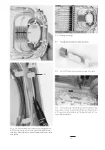
Страница 15: ...If necessary tubes can be bundled with 1 foam If loose tubes are added at a later date use other positions 5 1 7 If applicable remove all the premounted pigtails out of the storage area and mark the fibers at the splice holder Remove the secondary coating from this point This assures the transition primary secondary is in a straight line 5 1 8 Position all the pigtails under the splice protection ...

Страница 16: ... splice module 5 1 12 Strip the loose tubes and place 1 layer of foam around all the tubes at 50 mm from the end of the tubes 5 1 13 Secure all the tubes with the two tie wraps as shown In case not all fibers will be installed at day 1 5 1 16 Secure the added tubes also with one tie wrap as shown Preparation is the same as the first installed tubes 5 1 14 Strip the loose tubes and place 1 layer of...

Страница 17: ...a straight line 24 1 5 2 Installation of break out cable on the tray 5 2 1 Use the GTU kit for the termination of a group of 4 pigtails 5 2 2 Identify the 4 pigtails Bundle them with PVC tape Route them up to the tray mark the 4 pigtails on the GTU position Make sure there is 1 5 m pigtail available from this point The length is limited to 1 m in case of tight coated pigtail 5 1 18 Splicing and st...

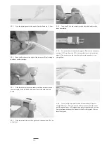
Страница 18: ...nt 5 2 7 Take the GTU at the metal clip and pull at the Kevlar until it locks completely 5 2 8 Cut excess Kevlar Identify the pigtails Remove the secondary coating 10 20 mm from the GTU only possible in case of semi tight pigtail This ensures you the transition primary to secundary is in a straight line 5 2 9 In case of pigtails with a limited amount of Kevlar typical outside diameter 2 2 mm wrap ...

Страница 19: ... at a later date without disturbing active circuits 1 3 2 5 3 1 For ease of installation start with the bottom tray If possible apply 1 wrap of foam tape around the IFC just before the jacket end This foam prevents from easy pull out and provides protection to the fibers inside Attach to the tray with 2 small tie wraps At least 1 tie wrap should be on top of the foam tape Cut the excess length of ...

Страница 20: ...ce module 5 3 7 You can separate each bundle of 900 micron by the split transition plate 1 1 1 5 3 8 Install the connectors of the first bundle 1 in the adapters and then route the overlength in the storage area Repeat this for the second bundle 2 Enter the storage area see picture above 5 4 Installation of ribbon cable on the tray 5 3 5 Splicing repair connectors is possible one can use the splic...

Страница 21: ... is shown 6 Storage 6 1 Storage can be done at the bottom of the shelf Secure with the Velcro 6 3 PATCH SPLICE storage of a patch cord entering the shelf at the right side is shown Check the position of the smalll bend control 6 4 In case of patch cords entering at the left hand side position the small bendcontrol at the right side 6 2 PATCH PATCH storage of a patch cord entering the shelf at the ...

Страница 22: ... push the adaptor simultaneously in the opposite direction 2 Place the adapter connector back in the tray by sliding and hinging it down along the vertical axis 7 Patching 7 2 Repeat this procedure with the other pigtails Respect routing of jumpers as shown on the picture Provide sufficient slack for patching to all other positions in the shelve 7 3 Routing of incoming pigtails and outgoing patchc...

Страница 23: ...n information on the ID cards 9 Important steps In case of loose tube termination side or back don t modify the predefined flex tube length apply foam tape to the flex tube apply foam tape to loose tubes Make sure the transition primary to secondary fiber is in a straight line under the splice holder in case of tight coated pigtail in the splice protector Cut excess length of tie wraps Make sure a...

Страница 24: ...ons of Sale for this product and in no case will Tyco Electronics be liable for any incidental indirect or consequential damages arising out of the sale resale use or misuse of the product Users of Tyco Electronics products should make their own evaluation to determine the suitability of each such product for the specific application Tyco Electronics Raychem NV Telecom Outside Plant Diestsesteenwe...

Отзывы: