


3.8.2
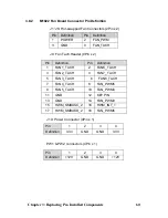
M1022 Fan Board Connector Pin Definition
J1~J8: Hot-swapped Fan Connectors (2Pin x 2)
Pin
Definition
Pin Definition
1 POWER
2 FAN_PWM
3 GND
4 FAN_TACH
J9: Fan Tach.Header (9Pin x 2)
Pin
Definition
Pin
Definition
1 FAN1_TACH
2 FAN6_TACH
3 FAN2_TACH
4 FAN7_TACH
5 FAN
3
_TACH
6 FAN8_TACH
7 FAN4_TACH
8 FAN_PWM5
9 FAN5_TACH
10 FAN_PWM4
11 GND
12 KEY
PIN
13 GND
14 FAN_PWM3
15 HWM_SMBUSC_2
16 HWM_INT_1
17 HWM_SMBUSD_2
18 FAN_PWM6
J10: Power Connector (4Pin x 1)
Pin
1
2
3
4
Definition
3.3V GND GND 3.3V
PW1 & PW2 connectors (4Pin x 1)
Pin
1
2
3
4
Definition
+12V GND GND +12V
Chapter 3: Replacing Pre-Installed Components
60
Содержание Transport TN27 B4987
Страница 1: ...Transport TN27 B4987 Service Engineer s Manual ...
Страница 2: ......
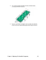
Страница 17: ...8 Rail Kit Rail with Bracket x 2 Screw Sack Chapter 1 Overview 8 ...
Страница 31: ...22 1 6 6 System Block Diagram Chapter 1 Overview 22 ...
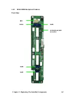
Страница 62: ...3 6 1 M1003 LED Control Board Features 53 Chapter 3 Replacing Pre Installed Components ...
Страница 127: ...The following diagrams may guide you how to install the InfiniBand Driver Welcome Screen License Agreement 118 ...
Страница 128: ...Registration Info Install Path SDP WSD Activation 119 ...
Страница 129: ...Complete Custom Components Selection Only SDP or WSD may be installed Not both Below SDK 120 ...
Страница 130: ...SDP WSD Activation The installer installs 3 types of devices InfiniBand Fabric HCA IPoIB Interface 121 ...