background image

1.5  About the product

6

Chapter 1: Overview

1.5

About the product

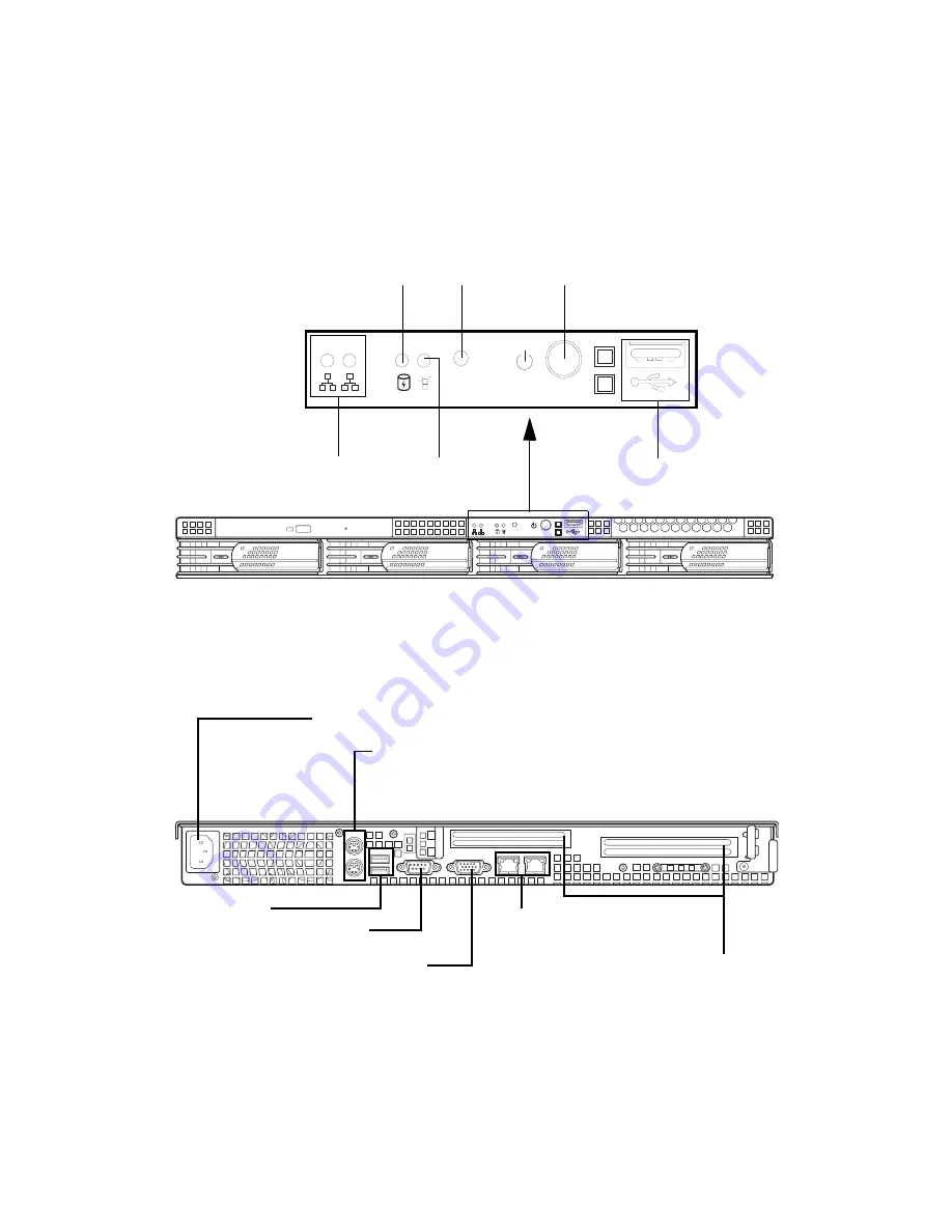
This section contains hardware diagrams and a block dia-
gram of the GX28 system.

1.5.1 System front view and front panel.

1.5.2 System rear view

1

2

RST

1

2

RST

USB port

Power button

HDD activity LED

Stacked PS/2 mouse and keyboard ports

USB ports

VGA port

Serial port (COM 1)

RJ-45 LAN ports

Expansion slots

Power supply socket

Reset

LAN activity

Power 
LED

Содержание Transport GX28 B2881

Страница 1: ...Transport GX28 B2881 User s Manual Document part number D1584 100 RST 1 2...

Страница 2: ...ake changes to product descriptions and or specifications at any time without notice In no event will TYAN be held liable for any direct or indirect incidental or consequential damage loss of use loss...

Страница 3: ...into an outlet on a circuit different from that of the receiver Consult the dealer on an experienced radio television technician for help Notice for Canada This apparatus complies with the Class B li...

Страница 4: ...scribes the external components shows a tables of key components and provides a block diagram of the sys tem Chapter 2 Setting up Covers procedures on installing the CPUs memory modules optional PCI X...

Страница 5: ...pose of this pin If your outlet does not support this type of plug contact an electrician to replace the obsolete outlet Do not place anything on the power cord Place the power cord where it will not...

Страница 6: ...2 2 Installing CPUs 14 2 2 3 Installing memory 17 2 2 4 Installing a PCI X PCI card 18 2 3 Installing a hard drive 21 2 3 1 Installing a SATA hard drive 21 2 3 2 Installing a SCSI hard disk 23 2 4 Ra...

Страница 7: ...s configuration submenu 64 USB configuration submenu 65 Onboard device submenu 66 BIOS PCI PnP menu 67 BIOS boot menu 69 Boot settings configuration submenu 69 BIOS security menu 71 BIOS chipset setti...

Страница 8: ...ATA or SCSI hard disk drives provide maximum flexibility and combine with gigabit Ether net ports to provide powerful computing capacity and optimal I O bandwidth for the most demanding enterprises Th...

Страница 9: ...ower management Power management S1 S4 and S5 support Memory 128 bit dual channel memory bus 8 184 pin 2 5V DDR DIMM sockets Up to 16 GB of registered DDR ECC type memory module support DDR 400 suppor...

Страница 10: ...4 hot swappable HDD bays Choice of motherboard pre installed B2881 G28S4H Tyan S2881G2NR B2881 G28U4H Tyan S2881UG2NR 24x slim CD ROM drive pre installed SATA or SCSI backplane and holding bracket pr...

Страница 11: ...s 2 Sliding rails Tyan K8S Pro S2881 motherboard user manual and Transport GX28 B2881 hardware installation guide 1 Air duct S2882 K8S Pro AJS D 1528 100 Revision 1 0 High Performance Motherboard User...

Страница 12: ...ure that all components are present and undamaged The product should arrive pack aged as illustrated below Contact your distributor if anything is missing or appears damaged http ww w tyan c om http w...

Страница 13: ...a block dia gram of the GX28 system 1 5 1 System front view and front panel 1 5 2 System rear view 1 2 RST 1 2 RST USB port Power button HDD activity LED Stacked PS 2 mouse and keyboard ports USB port...

Страница 14: ...board 8 Power supply A C connector 2 Slim CD ROM drive 9 System fan rear 3 Front panel cables 10 EPS 12V 400W power supply 4 SMDC card holder 11 System cooling fan assembly 5 Memory sockets 12 SATA b...

Страница 15: ...rear 2 Slim CD ROM drive 9 Power supply A C connector 3 Front panel cables 10 EPS 12V 400W power supply 4 Memory sockets 11 System cooling fan assembly 5 CPU sockets 12 SCSI backplane 6 PCI X slot 13...

Страница 16: ...4 bit Upper 64 bit Upper 64 bit Lower 64 bit 128 BitDualChannel 128 BitDualChannel PCI X 8131 PCI X Slot 2 Broadcom 5704C PCI X Slot 1 ATA 133 EIDE x2 USB 1 1 front rear BIOS EEPROM ADT 7463 Hardware...

Страница 17: ...Memo...

Страница 18: ...alfunc tions Use containers to keep small components separated Putting all small components in separate containers prevents them from becoming lost Adequate lighting and proper tools can prevent you f...

Страница 19: ...Avoid touching motherboard components IC chips connectors memory modules and leads The motherboard is pre installed in the system When removing the motherboard always place it on a grounded antistati...

Страница 20: ...ow to install CPUs memory mod ules and PCI X cards 2 2 1 Removing the chassis cover Follow these instructions to remove the GX28 chassis cover This step is required before any other procedures in this...

Страница 21: ...es how to install AMD Opteron proces sors and heatsinks in your GX28 system This section applies to all models 1 Remove the chassis cover as described in section 2 2 1 Removing the chassis cover 2 Rem...

Страница 22: ...2 2 Installing motherboard components Chapter 2 Setting up 15 4 Lift the CPU locking lever as shown 5 Place the CPU in the CPU socket ensuring that pin 1 is located as shown pin 1...

Страница 23: ...e socket 7 Repeat steps four to six for the second CPU 8 Apply thermal grease to the top of the CPUs and place the CPU heatsinks on the CPUs 9 Tighten the two screws on each heatsink to secure them in...

Страница 24: ...1 Remove the chassis cover as described in section 2 2 1 Removing the chassis cover 2 Locate the memory slots on the motherboard 3 Press the memory slot locking levers in the direction of the arrows a...

Страница 25: ...y module is properly seated in the slot 2 2 4 Installing a PCI X PCI card Follow the instructions in this section to install a PCI X or PCI card in your system using the supplied riser card 1 Remove t...

Страница 26: ...slot in which to install a card and remove the screws securing the clamp as shown 4 Loosen the clamp as shown Note There are two PCI X PCI card slots available and the retaining clamp is different for...

Страница 27: ...I X PCI card into place in the slot on the riser card Ensure that the card is seated properly in the slot on the riser card and that the riser card is properly seated in its slot on the motherboard 7...

Страница 28: ...d drives 2 3 1 Installing a SATA hard drive Note This section applies only to the B2881G28S4H model Follow these instructions to install an external SATA hard drive in your GX28 system 1 Press the dri...

Страница 29: ...drive in the drive tray Note If you are replacing an existing HDD you will need to remove the four screws that secure it in the drive bay and remove it 4 Insert four screws to secure the new unit in t...

Страница 30: ...ith SATA or SCSI backplane and cables pre installed 2 3 2 Installing a SCSI hard disk Note This section applies only to the B2881G28U4H model Only 80 pin SCSI hard drives are supported Follow these in...

Страница 31: ...the drive bay out 3 Place a SCSI drive in the drive tray Note If you are replacing an existing HDD you will need to remove the four screws that secure it in the drive bay and remove it 4 Insert four s...

Страница 32: ...ert the drive tray into the chassis Ensure that the rear connector of the new drive is firmly seated in the backplane Note The GX28 is shipped with SATA or SCSI backplane and cables pre installed SCSI...

Страница 33: ...stalled and that the unit has been fully tested Maintenance can be performed on the unit while in a rack but it is preferable to install the device in a fully operational condition 1 Attach the mounti...

Страница 34: ...end of the rail 3 Fully extend the sliding rails until they lock Note Do not tighten the brackets to the rails as you will need to adjust their position later 4 Attach each sliding rail to the side of...

Страница 35: ...Press the release mechanism A while pushing the sliding rails B to shorten them 6 With the rails in their shortest position adjust both front mounting brackets so that they are flush with the front of...

Страница 36: ...ting up 29 9 Lift the unit into place in the rack and secure it into place as shown Note To avoid injury it is strongly recom mended that two people lift the GX28 into place while a third person insta...

Страница 37: ...Memo...

Страница 38: ...your GX28 including PCI X cards riser card motherboard CD ROM drive and LED control board There is also a section covering the replacement of the 4 port SATA backplane and 4 port SCSI backplane Before...

Страница 39: ...s and the motherboard 3 2 1 Disconnecting all motherboard cables When replacing the motherboard or certain motherboard components it may be necessary to remove cables con nected to the motherboard Fol...

Страница 40: ...3 2 Replacing motherboard components Chapter 3 Replacing pre installed components 33 3 Disconnect SCSI cables if installed 4 Disconnect the front panel LED connectors...

Страница 41: ...ents 34 Chapter 3 Replacing pre installed components 5 Disconnect the CD ROM IDE cable 6 Disconnect fan power supplies Fan power supply pin headers are located at various points on your motherboard Se...

Страница 42: ...2 Removing motherboard components Follow these instructions to remove the air duct CPUs PCI riser card and memory modules Air duct 1 Remove the two screws that secure the air duct 2 Remove the air du...

Страница 43: ...ponents 36 Chapter 3 Replacing pre installed components 3 Lift the CPU locking lever as shown 4 Remove the CPU PCI riser card 1 Remove any PCI X cards from the riser card if they are installed 2 Remov...

Страница 44: ...rd Follow these instructions to remove the motherboard from your GX28 Note Before proceeding you must remove all cable connections to the mother board See section 3 2 1 Disconnecting all motherboard c...

Страница 45: ...er 3 Replacing pre installed components 4 Remove the single screw from the retaining clip for the PCI X PCI riser card and remove the clip 5 Remove the ten screws securing the motherboard to the chass...

Страница 46: ...drive This section describes how to remove and replace the CD ROM drive in your GX28 system 1 Remove the chassis cover as described in section 2 2 1 Removing the chassis cover 2 Remove the data and p...

Страница 47: ...nents 5 Remove the CD ROM drive backplane as shown 3 4 Replacing the LED control board Follow these instructions to replace the LED control board 1 Remove the chassis cover See Removing the chassis co...

Страница 48: ...rol panel to the chassis and lift the board free of the chassis 3 5 Replacing the front panel USB board Follow these instructions to replace the front panel USB board 1 Remove the chassis cover See Re...

Страница 49: ...nstructions to replace the SATA backplane on your GX28 Note This section applies only to the GX28 B2881 S4H 1 Remove the chassis cover as described in section 2 2 1 Removing the chassis cover 2 Discon...

Страница 50: ...alled components 43 6 Remove the three screws that secure the SATA back plane bracket to the chassis 7 Lift the backplane bracket free of the chassis as shown 8 Remove the six screws that secure each...

Страница 51: ...rage backplane 44 Chapter 3 Replacing pre installed components 3 6 1 1 SATA backplane features J3 serial ATA 7 pin connector J4 HDD2 serial ATA 7 pin connector JP1 LED output 2 x 6 pin header J5 DC in...

Страница 52: ...s serial ATA hard disk drive serial ATA interface plus serial ATA power 7 15 pin connectors Supports serial ATA interface 7 pin connectors Supports big 4 pin D type connector for DC power input 2 x 6...

Страница 53: ...features diagram Follow these instructions to replace the SCSI backplane on your GX28 Note This section applies only to the GX28 B2881 U4H 1 Remove the chassis cover as described in section 2 2 1 Rem...

Страница 54: ...led components 47 4 Remove the metal retaining plate as shown 5 Disconnect all cables from the SCSI backplane including two power cables and one SCSI data cable 6 Remove the ten screws securing the SC...

Страница 55: ...of dip switch functions see section 3 6 2 2 SCSI backplane specifi cations J10 SLIM FLOPPY DS1 DIP SW 5P J9 TO USB U14 MPU BZ1 BUZZER J8 BIG 4P 90DEG J7 BIG 4P 90DEG F3 FAN 3P F1 2 FAN 3P J6 FRONT PA...

Страница 56: ...play board Active terminator on board with auto detection for Ultra 320 160 backward compatibility Supports 3 configurations for ID setting of SCSI devices default is ID0 ID1 ID2 and ID3 If the add 4...

Страница 57: ...ct the power cables from the motherboard See Disconnecting all motherboard cables on page 32 3 Remove the four screws that secure the power supply to the chassis 4 Slide the power supply out and remov...

Страница 58: ...d the power supply are connected to the chassis 3 8 Replacing the cooling fans Follow these instructions to replace the cooling fans in your GX28 system 1 Remove the chassis cover as described in sect...

Страница 59: ...3 8 Replacing the cooling fans 52 Chapter 3 Replacing pre installed components 3 8 1 Pin header diagram Fan 1 Fan 4 Fan 2 Fan 9 Fan 3 Fan 5 Fan 6 Fan 8 Fan 7...

Страница 60: ...of the appendix describes the various BIOS settings that can be used to configure your system BIOS setup utility With the BIOS setup utility you can modify BIOS settings and control the features of y...

Страница 61: ...equired sub menu and press Enter Note A pointer marks all submenus Main Advanced PCI PnP Boot Security Chipset Power Exit System Overview Use Enter TAB or SHIFT_TAB to select a field Use or to config...

Страница 62: ...pset Configure chipset management features Power Configure power management settings Exit Exit setup utility Key Function F1 or Alt H General help window ESC Exit current window arrow keys Select a di...

Страница 63: ...ghlighted in white Often a text message will accompany it Main Advanced PCI PnP Boot Security Chipset Power Exit System Overview Use Enter TAB or SHIFT_TAB to select a field Use or to config ure syste...

Страница 64: ...tion IDE Configuration Floppy Configuration Super I O Configuration Hardware Health Configuration Event Log Configuration Device and PCI Slots Configuration Remote Access Configuration USB Configurati...

Страница 65: ...Both xxxx xxxx xxxx xxxx Disable xx Host Device Feature Option Description IDE Configuration Onboard PCI IDE Controller Both Primary Secondary Disabled This setting determines whether the AMD 8111 pri...

Страница 66: ..._TAB to select a field Use or to config ure system time Select Screen Select item Change option Tab Select field F1 General Help F10 Save and Exit ESC Exit Onboard floppy controller Floppy A Floppy B...

Страница 67: ...eral Help F10 Save and Exit ESC Exit Serial Port1 Address Serial Port2 Address Parallel Port Address Parallel Port Mode Parallel Port IRQ 3F8 IRQ4 3E8 IRQ3 378 Normal IRQ7 Feature Option Description W...

Страница 68: ...1 9 1 7 Assigns EPP version used by parallel port Main Advanced PCI PnP Boot Security Chipset Power Exit Hardware health Event Monitoring Use Enter TAB or SHIFT_TAB to select a field Use or to config...

Страница 69: ...s CPU2 Temperature System Temperature CPU1 Fan Speed Displays speed of fans connected to appropriate fan headers CPU2 Fan Speed FAN1 Speed FAN2 Speed FAN3 Speed FAN4 Speed CPU1 V_core Displays voltage...

Страница 70: ...ent Logging Use Enter TAB or SHIFT_TAB to select a field Use or to config ure system time Select Screen Select item Change option Tab Select field F1 General Help F10 Save and Exit ESC Exit View Event...

Страница 71: ...ss Terminal Type Serial Port Number Serial Port Mode Flow Control Post Boot Support Serial Feature Option Description Configure remote access type and parameters Remote access Disabled Serial Enables...

Страница 72: ...0 Save and Exit ESC Exit USB Function Legacy USB Support USB ZIP Emulation type USB Beep messages Enabled Auto Auto Disabled Feature Option Description USB Configuration USB Function Enabled Disabled...

Страница 73: ...Slot 64 bit PCI5 Slot 64 bit Onboard Gigabit LAN PXE Onboard Serial ATA Option ROM Enabled Enabled Enabled Enabled Enabled Enabled Enabled Enabled Enabled Feature Option Description Onboard Devices Su...

Страница 74: ...d F1 General Help F10 Save and Exit ESC Exit WARNING Setting wrong values in below sec tions may cause system to malfunction Plug Play OS PCI Latency Timer Allocate IRQ to PCI VGA Palette Snooping PCI...

Страница 75: ...s No Allows or restricts the system from giving the VGA adaptor an IRQ Palette Snooping Disabled Enabled This is the default setting and should not be changed unless the VGA card manufacturer requires...

Страница 76: ...ESC Exit Boot Settings Configuration Boot Device Priority Removable Drives Main Advanced PCI PnP Boot Security Chipset Power Exit Boot Settings Configuration Use Enter TAB or SHIFT_TAB to select a fi...

Страница 77: ...isabled Allows user to choose status of PS 2 mouse support Typematic Rate Fast Slow Choose the key repeat speed System keyboard Present Not present Enable or disable the keyboard error report Parity c...

Страница 78: ...ecurity Settings Use Enter TAB or SHIFT_TAB to select a field Use or to config ure system time Select Screen Select item Change option Tab Select field F1 General Help F10 Save and Exit ESC Exit Super...

Страница 79: ...first sector of the Hard Drive from being written Main Advanced PCI PnP Boot Security Chipset Power Exit Chipset Settings Use Enter TAB or SHIFT_TAB to select a field Use or to config ure system time...

Страница 80: ...d Use or to config ure system time Select Screen Select item Change option Tab Select field F1 General Help F10 Save and Exit ESC Exit Memory Configuration ECC Configuration IOMMU Configuration PCI X...

Страница 81: ...Exit Memory Configuration Use Enter TAB or SHIFT_TAB to select a field Use or to config ure system time Select Screen Select item Change option Tab Select field F1 General Help F10 Save and Exit ESC...

Страница 82: ...ription Southbridge Chipset Configuration 2 0 SM Bus Controller Enabled Disabled Enables or disables the SM bus 2 0 controller in the AMD8111 I O hub HT Link 0 P Comp Mode Auto Data CalComp Data CalCo...

Страница 83: ...Auto Feature Option Description PCI X Chipset Configuration HT Link 0 P Comp Mode Auto Data CalComp Data CalComp Data Auto uses hardware compensa tion values Other values add to or subtract from hardw...

Страница 84: ...PCI PnP Boot Security Chipset Power Exit PCI X Chipset Configuration Use Enter TAB or SHIFT_TAB to select a field Use or to config ure system time Select Screen Select item Change option Tab Select f...

Страница 85: ...ence power resources remain on and devices that can wake the system can cause the CPU to con tinue execution from where it left off C3 Allows the CPU to be put in a low power state In this state incom...

Страница 86: ...item Change option Tab Select field F1 General Help F10 Save and Exit ESC Exit ACPI 2 0 Support ACPI APIC Support BIOS AML ACPI table Yes Enabled Enabled Feature Option Description Advanced ACPI Confi...

Страница 87: ...itor IRQ 5 Monitor IRQ 6 Monitor IRQ 7 Monitor IRQ 8 Monitor IRQ 9 Monitor IRQ 10 Monitor IRQ 11 Monitor IRQ 12 Monitor IRQ 13 Monitor IRQ 14 Monitor IRQ 15 Monitor Ignore Ignore Ignore Monitor Ignore...

Страница 88: ...Discard Changes Load Optimal Defaults Load Failsafe Defaults Feature Description Save Changes and Exit Use this option to exit setup and reboot Changes you have made are stored into CMOS Discard Chan...

Страница 89: ...merchandise for service If any problems occur during the product s warranty period consult your system vendor or distributor before contacting TYAN The warranty covers normal customer use of the produ...

Отзывы: