background image

2.1.5.1  Installing the 3.5” Hard Drive (Left) 
 

Follow these instructions to install the left 3.5” SATA hard 
drive. 
 
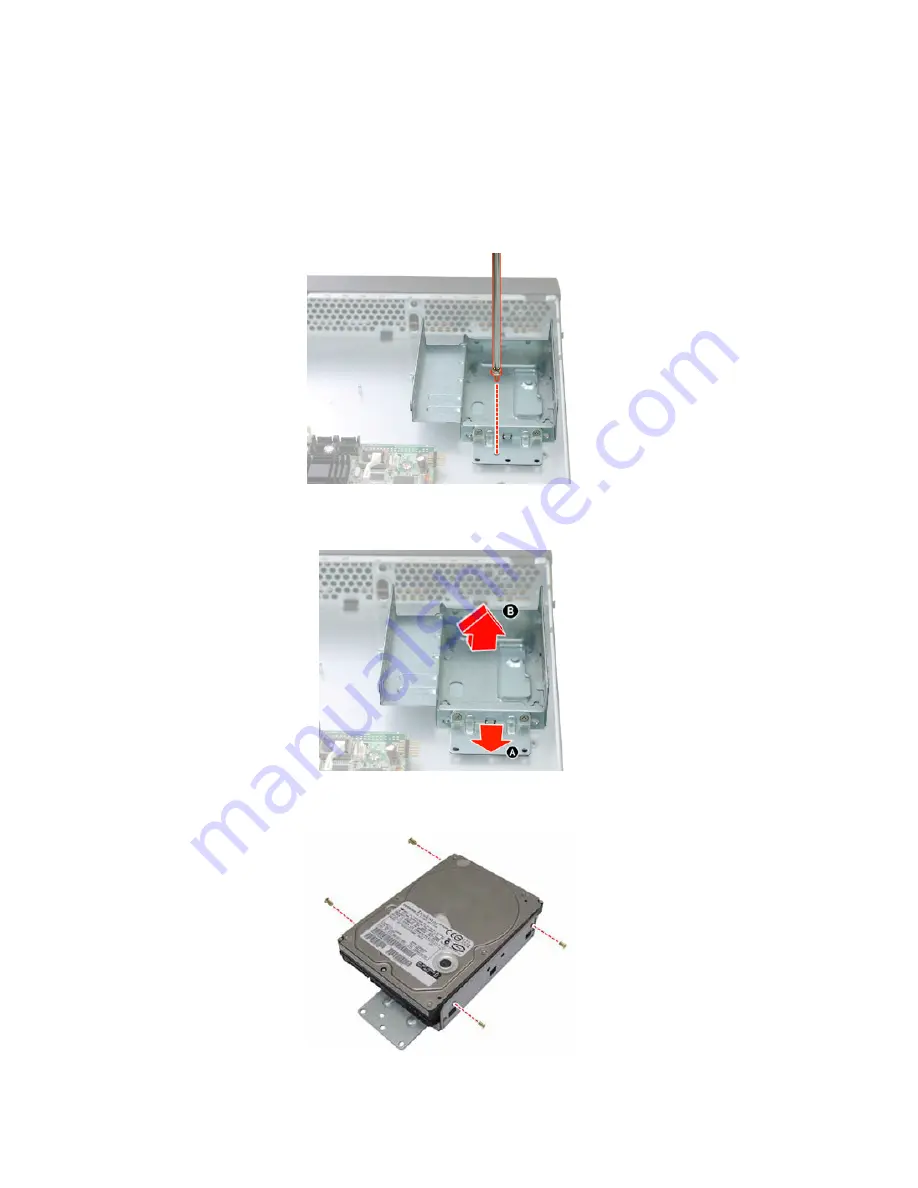
1.     Remove the screw securing the 3.5” drive bracket in the 

GT14 chassis. 


2.     Slide the drive tray out (A) and lift the bracket out from 

the chassis (B). 


3.     Place a 3.5” hard drive into the drive bracket and secure 

it with 4 screws. 


36

Chapter 2: Setting Up

Содержание Tank GT14 B5180

Страница 1: ...Tank GT14 B5180 Service Engineer s Manual...

Страница 2: ......

Страница 3: ...and or specifications at any time without notice In no event will TYAN be held liable for any direct or indirect incidental or consequential damage loss of use loss of data or other malady resulting...

Страница 4: ...to an outlet on a circuit different from that of the receiver Consult the dealer on an experienced radio television technician for help Notice for Canada This apparatus complies with the Class B limit...

Страница 5: ...e system Chapter2 Covers procedures on installing the CPU memory modules a PCI Express card and hard drives Rack mounting information is also provided in this chapter Chapter3 Covers removal and repla...

Страница 6: ...e your obsolete outlet Do not place anything on the power cord Place the power cord where it will not be in the way of foot traffic Follow all warnings and cautions in this manual and on the unit case...

Страница 7: ...ver 29 2 1 2 Installing the CPU and Heatsink 30 2 1 3 Installing the Memory 32 2 1 4 Installing the PCI E Card 33 2 1 5 Installing the Hard Drive 35 2 2 Rack Mounting 42 2 2 1 Installing the Server in...

Страница 8: ...x AwardBIOS CMOS Setup Utility 81 4 3 Advanced BIOS Features 82 4 3 1 CPU Features 85 4 3 2 Hard Disk Boot Priority 86 4 4 Advanced Chipset Features 87 4 5 Integrated Peripherals 88 4 5 1 OnChip IDE D...

Страница 9: ...dth memory design and lightning fast PCI E slot implementation The Tank GT14 B5180 not only empowers your company in today s demanding IT environment but also offers a smooth path for future applicati...

Страница 10: ...Cooling Configuration Air Duct 1 Air duct Type EPS12V Input Range Full range AC 100 240V Frequency 60 Hertz Power Supply Output Watts 300 Watts Supported CPU Series Intel Pentium 4 Pentium D and Core...

Страница 11: ...PMI over LAN Shared management NIC Properitary card interface 2 x 25pin header Brand ROM size Award 8MB BIOS Feature Plug and Play PnP PCI2 3 WfM2 0 SMBIOS2 3 PXE Boot ACPI 2 0 power management Power...

Страница 12: ...l cable 500mm Package Contains Cable Power Cord 1 CCBL 0310 US type power cord 1 CCBL 0300 EU type power cord SMDC IPMI Card M3291 Rack Mounting Part 1 CRAL 0110 GT14 Standard Rail kit for 4 Post 1 CB...

Страница 13: ...MSC SCH5027 Supported DIMM Qty 2 DIMM sockets DIMM Type Speed Unbuffered Non ECC DDR2 800 667 533 Capacity Up to 4GB Memory channel 2 Channel Memory Memory voltage 1 5V PCI E 1 PCI E x16 slot Expansio...

Страница 14: ...C 35 C 50 F 95 F Non operating Temp 40 C 70 C 40 F 158 F Operating Environment In Non operating Humidity 90 non condensing at 35 C RoHS RoHS 6 6 Complaint Yes Motherboard 1 S5180G2N BB Manual 1 User s...

Страница 15: ...le 500mm Package Contains Cable Power Cord 1 CCBL 0310 US type power cord 1 CCBL 0300 EU type power cord SMDC IPMI Card M3291 Rack Mounting Part 1 CRAL 0110 GT14 Standard Rail kit for 4 Post 1 CBRK 00...

Страница 16: ...service http www tyan com The Web site also provides information on other TYAN products plus FAQs compatibility lists BIOS settings and more 1 x Tyan Barebone Drive CD Power Cables Left to right Europ...

Страница 17: ...for 4 post rack Sliding Rails x 2 Sliding Brackets x 4 Front L Bracket x 2 Rear L Bracket x2 Mounting Brackets x 4 M4 4L screw x 18pcs M5 8L screw x 10pcs M5 15L screw x 4pcs B Rail for 3 post rack In...

Страница 18: ...2 Post Slide Mount Adapters x 4 Assembled Outer Sliding Rails x 2 M4 4L screw x 30pcs M5 8L screw x 10pcs M5 15L screw x 4pcs NOTE For detailed information on rail kit of C please contact our sales r...

Страница 19: ...w you the product 1 5 1 System Front View 1 5 2 System Rear View B5180G14S3M USB Port x 2 LCD Display Power Supply Fan Power Supply Socket PCI E Slot PS 2 Mouse Keyboard Ports Serial Port USB Port x 4...

Страница 20: ...B5180G14S3M QT Power Supply Socket Power Supply Fan PCI E Slot PS 2 Mouse Keyboard Ports Serial Port USB Port x 4 LAN Port x 2 VGA Port 12 Chapter 1 Overview...

Страница 21: ...ccessing No LAN linked Warning Red ON OFF System fails fan fail over voltage over temperature Normal ID LED Blue ON OFF System is identified System is not identified Rear I O LED LED Color State Descr...

Страница 22: ...Card 6 3 5 Hard Disk Drive Bracket Right 2 Air Duct 7 Chassis Front Bezel 3 Power Connector 8 3 5 Hard Disk Drive Bracket Left 4 Power Supply 9 System Fans 5 Memory Slot 10 2 5 Hard Disk Drive Bracke...

Страница 23: ...3 5 Hard Disk Drive Bracket Right 2 Air Duct 7 Chassis Front Bezel 3 Power Connector 8 3 5 Hard Disk Drive Bracket Left 4 Power Supply 9 System Fans 5 Memory Slot 10 2 5 Hard Disk Drive Bracket 1 2 5...

Страница 24: ...5 Motherboard Layout This diagram is representative of the latest board revision available at the time of publishing The board you receive may not look exactly like the above diagram 16 Chapter 1 Over...

Страница 25: ...ctor 8_Pin x 1 JP24 JP25 LANA SMBus Selection 5_Pin x 2 JP30 CMOS Clear J30 SMDC Connector 25_Pin x 2 J100 Chassis LCD Module Interface Header 3_Pin x 2 J101 Front Panel Header 2 6_Pin x 2 Jumper Lege...

Страница 26: ...Header 5Pin x 2 Signal Pin Pin Signal 5VPWR 1 2 5VPWR DATA1 3 4 DATA2 DATA1 5 6 DATA2 GND 7 8 GND Key 9 10 GND Use this header to connect to the USB devices via the enclosed USB cable JP16 JP23 JP13 J...

Страница 27: ...5 6 PWR S W Reset S W 7 8 PWR S W 3 3V 9 10 WLED EXT_NMI 11 12 WLED 5VSB 13 14 KEY SDA 15 16 GND SCL 17 18 INTRUDER JP23 FAN Connector 4Pin x 1 Pin_1 Pin 1 2 3 4 Signal GND 12V TACH PWM J102 J103 FAN...

Страница 28: ...n 3Pin x 1 Pin_1 Pin_3 Use jumper cap to close Pin_1 and Pin_2 Connect LANA SMBus to motherboard SMBus Pin_1 Pin_3 Use jumper cap to close Pin_2 and Pin_3 Connect LANA SMBus to SMDC SMBus JP25 JP30 J3...

Страница 29: ...f system and disconnect both power connectors from the motherboard Put jumper cap back to Pin_1 and Pin_2 default setting Use jumper cap to close Pin_2 and Pin_3 for several seconds to Clear CMOS Reco...

Страница 30: ...n x 2 Signal Pin Pin Signal 5VPWR 1 2 SIN KEY 3 4 GND 5VSB 5 6 SOUT J101 Front Panel Header 2 6Pin x 2 Signal Pin Pin Signal LAN1_LED 1 2 LAN1_LED LAN2_LED 3 4 LAN1_LED NC 5 6 NC IDLED 7 8 IDLED IDSW...

Страница 31: ...1 5 7 System Block Diagram Chapter 1 Overview 23...

Страница 32: ...2 5 HDD Dual Bracket CPSU 0300 1 300W Single Power Supply B5180G14S3M SKU Power Supply CPSU 0400 1 250W Single Power Supply B5180G14S3M QT SKU CFAN 0310 2 40X40X56mm Fan 15800rpm 8 pin CFAN 0270 2 40...

Страница 33: ...ting Parts CEAR 0120 1 Mounting Ear Kit CCBL 0727 1 Front Control Board Cable 500mm CCBL 0352 1 USB Board Cable 350mm CCBL 0606 1 LCM Cable 470mm CCBL 0310 1 A C Power Cord US Type 2440mm CCBL 0300 1...

Страница 34: ...26 Chapter 1 Overview...

Страница 35: ...arate containers prevents them from becoming lost Adequate lighting and proper tools can prevent you from accidentally damaging the internal components 2 0 3 Tools The following procedures require onl...

Страница 36: ...ce z Avoid touching motherboard components IC chips connectors memory modules and leads z The motherboard is pre installed in the system When removing the motherboard always place it on a grounded ant...

Страница 37: ...PCI E card 2 1 1 Removing the Chassis Top Cover Follow these instructions to remove the Tank GT14 B5180 chassis top cover 1 Remove the screw on the back side as shown in the small diagram and tow on...

Страница 38: ...install CPU and CPU heatsink 1 Remove the air duct in the direction of the arrow shown to locate the CPU socket 2 Remove the CPU socket cover 3 Pull the CPU lever up to unlock the CPU socket A and op...

Страница 39: ...PU socket lever down to secure the CPU B 5 Place the heatsink on the top of the CPU and attach with four screws as shown 6 Place the air duct on the heatsink and press it down in the direction as the...

Страница 40: ...e memory slot locking levers in the direction of the arrows as shown in the following illustration 2 Align the memory module with the slot When inserted properly the memory slot locking levers lock au...

Страница 41: ...s to install the PCI E card 1 Remove the screw securing the tab of PCI E slot from the rear side of your GT14 B5180 system 2 Pull the tab of PCI E slot on the rear side in the direction as shown to re...

Страница 42: ...E riser in the direction of arrows as shown 5 Push the tab of PCI slot on the rear side in the direction as shown to fix the PCI E Card And secure the tab of PCI E slot on the rear side with one screw...

Страница 43: ...upport Refer to the following HDD Configuration Table and Location Diagram before installing Hard Driver HDD Configuration Table 3 5 HDD Left 3 5 HDD Right 2 5 HDD No SMDC Default Chassis SMDC Support...

Страница 44: ...all the left 3 5 SATA hard drive 1 Remove the screw securing the 3 5 drive bracket in the GT14 chassis 2 Slide the drive tray out A and lift the bracket out from the chassis B 3 Place a 3 5 hard drive...

Страница 45: ...d hard drive with bracket in the spot you picked from the GT14 chassis A and slide it into place B And secure it with the screw removed in step 1 5 Connect the SATA drive data and power connectors Cha...

Страница 46: ...l the right 3 5 SATA hard drive 1 Remove the two screws securing the 3 5 drive bracket in the GT14 chassis 2 Slide the drive tray out A and lift the bracket out from the chassis B 3 Place a 3 5 hard d...

Страница 47: ...hard drive with bracket in the spot you picked from the GT14 chassis A and slide it into place B And secure it with the two screw removed in step 1 5 Connect the SATA drive data and power connectors C...

Страница 48: ...all the 2 5 SATA hard drive 1 Remove the screw securing the 2 5 drive bracket in the GT14 chassis 2 Slide the drive tray out A and lift the bracket out from the chassis B 3 Place a 2 5 hard drive into...

Страница 49: ...d hard drive with bracket in the spot you picked from the GT14 chassis A and slide it into place B And secure it with the screw removed in step 1 5 Connect the SATA drive data and power connectors Cha...

Страница 50: ...for your reference Screws List For the complete contents in the rack mounting kit see 1 4 Unpacking for more information Rail for 4 post rack Rail kit A Item Screw Size Quantity A M4 4L 18 B M5 8L 10...

Страница 51: ...installed and that the unit has been fully tested Maintenance can be performed on the unit while in a rack but it is preferable to install the device in a fully operational condition Installing the I...

Страница 52: ...3 Install inner rails to left and right sides of chassis using 1 M4 4L A screw for each side 44 Chapter 2 Setting Up...

Страница 53: ...5 Reserve the distance same as in step 4 on rear racket Secure the rear bracket to outer rail with 2 M4 4L A screws 6 Secure the outer rails to the rack using 2 brackets and 5 M5 8L B screws for each...

Страница 54: ...the middle rails to the latch position 8 Lift the chassis and then insert the inner slide rails into the middle rails 9 Push the chasis in and press the latch key A Then push the whole system into the...

Страница 55: ...rs of chassis to the rack with one M4 15L F screw for each side NOTE To avoid injury it is strongly recommended that two people lift the GT14 into the place while a third per son screws it to the rack...

Страница 56: ...Before mounting the Transport GT14 in a rack ensure that all internal components have been installed and that the unit has been fully tested Maintenance can be performed on the unit while in a rack bu...

Страница 57: ...OTE To avoid injury it is strongly recommended that two people lift the GT14 into the place while a third per son screws it to the rack 3 Locate the three small brackets at the rear of rack as shown A...

Страница 58: ...e mounting brackets into the rear of inner rail brackets as shown 5 Secure the mounting brackets with three M4 4L E screws for each side 6 The GT14 has been mounted to the rack as shown 50 Chapter 2 S...

Страница 59: ...ed for safe operation of the equipment is not compromised C Mechanical Loading Mounting of the equipment in the rack should be such that a hazardous condition is not achieved due to uneven mechanical...

Страница 60: ...fore You Begin Before you begin make sure that you have the following information ready IP address assigned to the system Subnet mask of your network 2 3 2 M1000 Driver Installation for Windows Step 1...

Страница 61: ...lection 3 Right Enter Go to the next level selection press again to execute command 4 Down Go to the next selection After you have installed the TYAN TSM and M1000 driver for Windows for Windows OS or...

Страница 62: ...both DOS Mode and Windows Mode DOS Mode DOS Mode No Item Screen Display 1 BIOS Info V1 02 B11 2 Model Name Tank GT14 MODEL B5180 3 CPU Info CPU xxxx MHz 4 Memory Info Memory xxxx MB Model Name RAM In...

Страница 63: ...xxx Net Mask xxx xxx xxx 0 Gateway xxx xxx xxx 0 1 2 NIC1 DHCP IP Address xx xx x xxx Net Mask xxx xxx xxx 0 Gateway xxx xxx xxx 0 System Nics Performance Power Ctl System Sensors Windows Mode Host N...

Страница 64: ...Bps System Sensors 3 1 Fan Chassis Fan 1 Chassis Fan 2 Chassis Fan 3 Chassis Fan 4 Chassis Fan 5 xxxxRPM xxxxRPM xxxxRPM xxxxRPM xxxxRPM 3 2 Voltage CPU Core Volt System Volt 12V System Volt 5V 5V Sta...

Страница 65: ...x x xxx Net Mask xxx xxx xxx 0 Gateway xxx xxx xxx 0 1 2 NIC1 DHCP IP Address xx xx x xxx Net Mask xxx xxx xxx 0 Gateway xxx xxx xxx 0 System Nics Performance Power Ctl System Sensors Linux Mode Host...

Страница 66: ...Bps System Sensors 3 1 Fan Chassis Fan 1 Chassis Fan 2 Chassis Fan 3 Chassis Fan 4 Chassis Fan 5 xxxxRPM xxxxRPM xxxxRPM xxxxRPM xxxxRPM 3 2 Voltage CPU Core Volt System Volt 12V System Volt 5V 5V Sta...

Страница 67: ...separate containers prevents them from becoming lost Adequate lighting and proper tools can prevent you from accidentally damaging the internal components 3 1 2 Tools The following procedures require...

Страница 68: ...ouching motherboard components IC chips connectors memory modules and leads z The motherboard is pre installed in the system When removing the motherboard always place it on a grounded anti static sur...

Страница 69: ...e disassembly procedure Rear Components Chassis top cover Power Supply Mainboard DIMMs CPU Heatsink Assembly Mainboard Front Components Chassis front bezel PCBs FANs LCD Module USB Board PCI E Card Fr...

Страница 70: ...instructions to remove the cover of the Tank GT14 chassis cover 1 Remove the screw on the back side as shown in the small diagram and two on the top of the chassis top cover 2 Slide the chassis top co...

Страница 71: ...e replacing the motherboard or certain components remove cables connected to the motherboard Follow these instructions to remove all motherboard cabling 1 Disconnect Power Cables 2 Disconnect the FAN...

Страница 72: ...ng all of the aforementioned cables follow these instructions to remove the motherboard from the chassis 1 Remove the five screws securing the motherboard to the chassis 2 Remove the motherboard 64 Ch...

Страница 73: ...tructions to replace the LCD module and LED Board in your GT14 B5180 system 1 Remove the chassis front bezel as shown 2 Remove the two screws securing the LCD module 3 Disconnect the LCM and control b...

Страница 74: ...emove the four screws on both sides of the LCD module 5 Remove the LCD front bracket from the LCD module 6 Remove the two screws from the rear LCD bracket 66 Chapter 3 Replacing Pre Installed Componen...

Страница 75: ...ree screws securing the LED board to the rear LCD bracket Remove the LED board 8 Place a new LCD module in position in the chassis following the above steps in reverse Chapter 3 Replacing Pre Installe...

Страница 76: ...D Board Features 3 5 2 M1017 LED Board Connector Pin Definition 2 x 14 Pin Header Warning LED LAN1 LED LAN2 LED ID Button Power Button HDD Access LED ID LED Power LED 68 Chapter 3 Replacing Pre Instal...

Страница 77: ...ezel as step 1 in 3 5 Replacing the LCD Module and LED Board 2 Disconnect the USB cable from the USB board 3 Remove the two screws securing the USB board to separate the USB board from the chassis 4 P...

Страница 78: ...Definition 2 x 5 Pin USB Header Pin Definition Pin Definition 1 USB1 POWER 2 USB2 POWER 3 USB1 DATA 4 USB2 DATA 5 USB1 DATA 6 USB2 DATA 7 USB1 GND 8 USB2 GND 9 KEY PIN 10 NONE USB 2x5 Pin Headers USB...

Страница 79: ...but the detailed fans cable connections please refer to Appendix I Table 3 1 Remove the three fan connectors from the motherboard 2 Remove the fan unit from the chassis 3 Remove the fan you want to re...

Страница 80: ...o the B5180G14S3M QT SKU 1 Disconnect the power cables from the motherboard Refer to 3 4 1 Disconnecting All Motherboard Cables for more details 2 Remove the two screws securing the power supply to th...

Страница 81: ...ower bracket as below 4 Lift the power supply with its bracket free from the chassis 5 Free the power supply from its bracket by removing the two screws 6 Replace a new power supply into the chassis f...

Страница 82: ...74 Chapter 3 Replacing Pre Installed Components...

Страница 83: ...dard BIOS for IBM PC AT compatible personal computers The BIOS provides critical low level support for the system s central processing unit CPU memory and I O subsystems This BIOS has been customized...

Страница 84: ...r settings that you thoroughly understand In particular do not change settings in the Chipset section unless you are absolutely sure of the outcome The Chipset defaults were carefully chosen by TYAN o...

Страница 85: ...atures Use this menu for basic system configuration Advanced BIOS Features Use this menu to set the Advanced Features available on your system Advanced Chipset Features Use this menu to change the val...

Страница 86: ...for optimal performance system operations While Award has designed the custom BIOS to maximize performance the factory has the right to change these defaults to meet their needs Supervisor User Passwo...

Страница 87: ...DE Channel 0 Master IDE Channel 0 Slave IDE Channel 1 Master IDE Channel 1 Slave IDE Channel 2 Master IDE Channel 3 Master Video Halt On Based Memory Extended Memory Total Memory Thu Apr 26 2007 6 33...

Страница 88: ...drive F None Auto Manual Video Define the video display mode EGA VGA CGA 40 CGA 80 MONO Halt On Determine if the computer should stop when an error is detected during power up No Errors All Errors All...

Страница 89: ...is channel Move Enter Select PU PD Value F10 Save ESC Exit F1 General Help F5 Previous Values F6 Fail Safe Defaults F7 Optimized Defaults IDE HDD Auto Detection Press Enter to select this option for a...

Страница 90: ...ol For OS OS Select For DRAM 64MB Press Enter Press Enter Disabled Enabled Enabled Enabled CDROM Hard Disk LS120 Enabled On Fast Disabled 6 250 Setup Enabled 1 4 Non OS2 Item Help ___________ ________...

Страница 91: ...e keyboard controller controls Gate A20 Setting Gate A20 to Fast improves system speed particularly with OS 2 and Windows Normal Fast Typematic Rate Setting Toggles control of keyboard key repeat rate...

Страница 92: ...sion of the IBM OS 2 operating system you should select OS 2 If you are using the IBM OS 2 Warp v3 0 or higher operating system you should select Non OS 2 If you are using an older version of the IBM...

Страница 93: ...10 Save ESC Exit F1 General Help F5 Previous Values F6 Fail Safe Defaults F7 Optimized Defaults Limit CPUID MaxVal Set Limit CPUID MaxVal to 3 should be Disabled for Win2003 Enabled Disabled C1E Funct...

Страница 94: ...___ Menu Level Use or to select a device then press to move it up or to move it down the list Press ESC to exit this menu Move Enter Select PU PD Value F10 Save ESC Exit F1 General Help F5 Previous Va...

Страница 95: ...bled allows caching of the system BIOS ROM at F0000h FFFFFh resulting in better system performance However if any program writes to this memory area a system error may result Enabled Disabled Memory H...

Страница 96: ...d Device SuperIO Device Watch Dog Timer Select LCM Module Support USB Device Setting Press Enter Press Enter Press Enter Disabled Enabled Press Enter Item Help ___________________ ______ Menu Level Mo...

Страница 97: ...alue F10 Save ESC Exit F1 General Help F5 Previous Values F6 Fail Safe Defaults F7 Optimized Defaults IDE HDD Block Mode Select Disabled or Enabled IDE HDD Block Mode Enabled Disabled IDE DMA Transfer...

Страница 98: ...ntroller and the CPU perform the complete task by itself This is simpler and more efficient and faster Your system includes a secondary built in IDE controller which operates on the PCI bus Enabled Di...

Страница 99: ...ce you may have problems running that device However if you don t use any USB devices set the option to Disabled It will free up an IRQ for other devices to use Enabled Disabled Note This option is fo...

Страница 100: ..._ Menu Level Move Enter Select PU PD Value F10 Save ESC Exit F1 General Help F5 Previous Values F6 Fail Safe Defaults F7 Optimized Defaults Press Power Button key to resume from S3 state Wake UP FROM...

Страница 101: ...by Ring USB KB Wake Up From S3 Resume by Alarm X Date of month Alarm X Time hh mm ss Alarm Enabled Auto User Define DPMS Yes Stop Grant 3 Disabled Disabled Instant Off Disabled Former Sts Enabled Disa...

Страница 102: ...ff the screen Yes System BIOS turns of the screen when system is in SUSPEND mode Suspend Type This option defines the system suspend type The two suspend types are Power on Suspend If this is selected...

Страница 103: ...resumed On Off Former Sts Wake Up by PCI card When set at Enabled any PCI PM event awakes the system from a PCI PM controlled state The options are Disabled Enabled Enabled Disabled Power On by Ring A...

Страница 104: ...yload Size 128 PCI Slot Disabled Auto ESCD Press Enter Disabled Auto Auto Auto Auto Auto Auto Auto Auto Item Help _____________ ____________ Menu Level Move Enter Select PU PD Value F10 Save ESC Exit...

Страница 105: ...he time that an application must wait for data to begin being transferred 4 8 PC Health Status This menu is related to detecting system temperature voltage fan and speed Phoenix AwardBIOS CMOS Setup U...

Страница 106: ...em Help _____________________ ____ Menu Level Move Enter Select PU PD Value F10 Save ESC Exit F1 General Help F5 Previous Values F6 Fail Safe Defaults F7 Optimized Defaults Note The onboard SMSC SCH50...

Страница 107: ...ll 10 15 Item Help ___________________ ______ Menu Level Move Enter Select PU PD Value F10 Save ESC Exit F1 General Help F5 Previous Values F6 Fail Safe Defaults F7 Optimized Defaults AutoFan Control...

Страница 108: ...evel Move Enter Select PU PD Value F10 Save ESC Exit F1 General Help F5 Previous Values F6 Fail Safe Defaults F7 Optimized Defaults CPU Clock Ratio The CPU clock ratio setting defines how fast the CPU...

Страница 109: ...the most stable minimal performance system operations 4 11 Load Optimized Defaults Phoenix AwardBIOS CMOS Setup Utility Standard CMOS Features Advanced BIOS Features Advanced Chipset Features Integra...

Страница 110: ...Password Can enter and change the options of the setup menus Set User Password Can enter but does not have permission to change any options When you select this function the following message will ap...

Страница 111: ...ou can also require the BIOS to request a password every time your system is rebooted This would prevent unauthorized use of your computer You determine when the password is required within the BIOS F...

Страница 112: ...S Features Advanced Chipset Features Integrated Peripherals Power Management Setup PnP PCI Configurations PC Health Status Frequency Voltage Control Load Fail Safe Defaults Load Optimized Defaults Set...

Страница 113: ...4S3M HDD Connect to Motherboard Fan 1 JP23 Fan 2 Fan 3 J103 Fan 4 Fan 5 J102 Table 3 System Fan to Motherboard For B5180G14S3M QT HDD Connect to Motherboard Fan 1 JP23 Fan 2 J103 Fan 3 JP22 Power Supp...

Страница 114: ...rboard JP16 Connector M1017 LED Connector J101 Connector Table 6 USB Board Related Cable USB Board Motherboard USB 2 x 5 pin header JP13 Connector Table 7 LCD Module Related Cable LCD Module Motherboa...

Страница 115: ...our GT14 chassis 1 Remove the screw securing the 2 5 hard disk drive bracket in the GT14 chassis Then slide the drive tray out A and lift the bracket out from the chassis B 2 Secure the three flat scr...

Страница 116: ...with three screws 4 Connect the 2 x 25 pin SMDC cable to M3291 as shown 5 Connect the other end of SMDC cable to the SMDC connector J30 on the motherboard Cable Connection Table SMDC Card M3291 to Mot...

Страница 117: ...the M2061 riser card 1 Remove the M2083 PCI E riser card from the PCI E riser card slot 2 Insert the M2061 riser card to the PCI Express slot as shown 3 Connect the small 4 pin connector of the power...

Страница 118: ...on detaching LAN cable 1 Refer to the first three steps in 2 1 4 Installing the PCI E Card to remove the I O shield 2 Use the I O shield as the tool to press the tab on the LAN Cable A and draw out t...

Страница 119: ...lowing illustration to assemble them when necessary NOTE Make sure the tab fit into the hole of the other fan holder A and lock 1 into 2 B B5180G14S3M Fan Holder B5180G14S3M QT Fan Holder Disassemble...

Страница 120: ...such as in depth Linux Online Support sections with downloadable Linux drivers and comprehensive compatibility reports for chassis memory and much more With all these convenient resources just a few...

Страница 121: ...the alteration misuse abuse or improper maintenance of products NOTE A receipt or copy of your invoice marked with the date of purchase is required before any warranty service can be rendered You may...

Отзывы: