background image


TWIN BUSCH GMBH


Technical changes, errors and printing mistakes are reserved.  V01_NK_418_EN


An expert 

is somebody with the training and experience required to possess specialist knowledge of lifting platforms and who 

is sufficiently familiar with the pertinent national work safety regulations, accident prevention regulations and generally 

acknowledged rules of engineering to be able to check and give an expert option on lifting platforms. 

3.  Important safety notices 


 Recommend for indoor use only, DO not expose the lift to rain, snow or excessive moisture. 


 Only use this lift on a surface that is stable, level and dry and not slippery, and capable of sustaining the load. Do not 

install the lift on any asphalt surface. 

3.2.  Read and understand all safety warnings before operating the lift. 


3.3.  Do not leave the controls while the lift is still in motion. 


3.4.  Keep hands and feet away from any moving parts. Keep feet clear of the lift when lowering. 


3.5.  Only these properly trained personnel can operate the lift. 


3.6.  Do not wear unfit clothes such as large clothes with flounces, tires, etc, which could be caught by moving parts of the lift. 


3.7.  To prevent evitable incidents, surrounding areas of the lift must be tidy and with nothing unconcerned. 


3.8.  The lift is simply designed to lift the entire body of vehicles, with its maximum weight within the lifting capacity. 


3.9.  Always insure the safety locks are engaged before any attempt to work near or under the vehicle. Never remove safety 

related components from the lift. Do not use if safety related components are damaged or missing. 

3.10.  Do not rock the vehicle while on the lift or remove any heavy component from vehicle that may cause excessive weight shift. 


3.11.  Check at any time the parts of the lift to ensure the agility of moving parts and the performance of synchronization. Ensure 

regular maintenance and if anything abnormal occurs, stop using the lift immediately and contact our dealers for help. 

3.12.  Lower the lift to its lowest position and do remember to cut off the power source when service finishes. 


3.13.  Do not modify any parts of the lift without manufacturer’s advice. 


3.14.  If the lift is going to be left unused for a long time, users are required to: 


a. Disconnect the power; 


b. Empty the oil tank; 


c. Lubricate the moving parts with grease. 


WARNING

the warnings, cautions and instructions discussed in this instruction manual cannot cover all possible 

conditions and situations that may occur. It must be understood by the operator that common sense and caution are 

factors which cannot be built into this product, but must be supplied by the operator. 

Attention: For environment protection, please dispose the disused oil in a proper way. 

Содержание TW SA 42 U V2

Страница 1: ......

Страница 2: ...TWIN BUSCH GMBH Technical changes errors and printing mistakes are reserved V01_NK_418_EN ...

Страница 3: ... General descriptions 10 2 Construction of the lift 10 3 Dimensions 11 4 Technical data 12 INSTALLATION INSTRUCTIONS 12 1 Preparations before installation 12 2 Installation attentions 13 3 General Installation Steps 14 4 Items to be checked after installation 15 OPERATION INSTRUCTIONS 16 1 Precautions 16 2 Descriptions of control panel 16 3 Flow chart for operation 17 4 Operation instructions 17 T...

Страница 4: ... expert or qualified person to perform checking The user bears special responsibility if employees of the company are appointed as experts or qualified persons 2 1 Scope ofchecking Regular checking essentially involves performing a visual inspection and a functional test This includes checking the condition of the components and equipment checking that the safety systems are complete and functioni...

Страница 5: ...h nothing unconcerned 3 8 Theliftissimplydesignedtolifttheentirebodyofvehicles withitsmaximumweightwithintheliftingcapacity 3 9 Always insure the safety locks are engaged before any attempt to work near or under the vehicle Never remove safety related components from the lift Do not use if safety related components are damaged or missing 3 10 Do not rock the vehicle while on the lift or remove any...

Страница 6: ...ng labels AllsafetywarningLabelsareclearlydepictedonthelifttoensurethattheoperatorisawareofandavoidthedangers ofusingtheliftinanincorrectmanner Thelabelsmustbekeptcleanandtheyhavetobereplacedifdetachedor damaged Please read carefully the meaning of each label and memories them for future operation ...

Страница 7: ... dangerofcrushing In the event of excessive vehicle weight incorrect mounting of the vehicle or on removing heavy object there is a risk of the vehicle falling off the lifting platform or tipping up Safety measures Theliftingplatformisonlyevertobeemployedfortheintendedpurpose Carefully study and heed all the information given in Section 1 4 Observe the warning notices for operation 1 6 Noise level...

Страница 8: ...se all appropriate precautions never stack to more than 2 meters in height never make stacks of single packs Always stack pairs of packs in a cross pattern so that the base is bigger and the resulting stack is more stable Once the stack is complete restrain it using straps ropes or other suitable methods A maximum of two packs can be stacked on lorries in containers and in railway wagons on condit...

Страница 9: ... unit The gear pump works when power supply is connected and meanwhile oil in the pump pushes upwards the pistons of oil cylinders Thus scissor brackets of the lift rise accordingly The mechanical lock will automatically engaged in case of failure of hydraulic system Besides designs like 24V working voltage of control box and limit switch low height alarming buzzer anti surge valves etc have fully...

Страница 10: ... 11 TWIN BUSCH GMBH Technical changes errors and printing mistakes are reserved V01_NK_418_EN 3 Dimensions ...

Страница 11: ...00mm 74 80 in Full lowered height 180mm 7 08 in Full raised time with rated load 55s Full lowered time with rated load 55s Hydraulic working pressure Bar 200 Bar 2900 75 PSI Pneumatic working pressure Bar 6 8 Bar 87 116 PSI Rated capacity of the secondary lift 4000KG 8818 49 Lbs Full raised height of the secondary lift 450mm 17 71 in Oil tank volume 18L 4 75 Imp gal ...

Страница 12: ...eiling it is advisable to fit an overhead light barrier in low ceiling buildings 1 1 Foundations and connections The user must have the following work performed before erecting the lift Construction of the foundation following consultation with the manufacturer s customer service or an authorized service agent Routingofthewiringtotheinstallationlocation Theusermustprovidefuseprotectionfortheconnec...

Страница 13: ...nd check if any parts missed as per the following list Do not hesitate to contact us in case any parts missed but if you do not contact us and insist installing upon the lack of some parts we as well as our dealers will not bear any responsibility for this and will charge for any parts subsequently demanded by the buyer S N Name Specification Qty 1 Lifting platform 6604 2 2 Expansion bolt M16 120 ...

Страница 14: ...ors and printing mistakes are reserved V01_NK_418_EN 2 Installation attentions Joints of oil hose and wiring must be firmly connected in order to avoid leakage of oil hose and looseness of electrical wires All bolts should be firmly screwed up ...

Страница 15: ...d another 4L into the tank Note As running speed of the lift is mainly decided by the density hydraulic oil we suggest using NO 46 hydraulic oil when average Temperature of the location is above 18 degree Celsius and using NO 32 hydraulic oil when temperature is below 18 degree Celsius Step 6 Leveling Check the connection of the hydraulic and electrical system before leveling operation Review oper...

Страница 16: ... check the synchronization 7 IF still not being synchronized repeat step 4 to step 6 until both platforms are synchronized Leveling platforms of the secondary lift central jack 1 TurnSA2oncontrolpaneltoJACKandturnSA1tolevelingstatus 2 PressUPbuttonuntilbothplatformofthejackgoutmosttoptobleedairinthecylinders 3 Press DOWN I until jacks lower to the lowest position PRESS UP BUTTON TO CHECK THE JACKS...

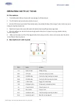
Страница 17: ...rms are raised to the desired height switch off the power to prevent any wrong operation done by unconcerned people 6 Make sure the safety lock of the lift is engaged before start working under the vehicle and no people under the vehicle during lifting and lowering process 2 Descriptions of control panel POS Name Function FA Alarm buzzer Safety warning SB1 UP button Control the rising movement SB3...

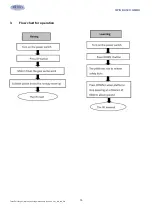
Страница 18: ... 19 TWIN BUSCH GMBH Technical changes errors and printing mistakes are reserved V01_NK_418_EN 3 Flow chart for operation ...

Страница 19: ...kis engaged Press the EmergencyStop andcheckagainthestabilitybeforeperformingmaintenanceorrepairwork Lowering 1 Switchon 2 Push DOWNI buttontolowerthelift Firstly theliftwillautomaticallyrisetodisengagethemechanicallocks Thentheliftlowers It will stop lowering when clearance between the platforms and the ground reaches to 600mm 3 Push DOWNII buttontocontinueloweringtheplatforms Alarmingbuzzwillbeh...

Страница 20: ...on Overflow valve is loose or jammed Clean or adjust it The gear pump is damaged Replace it Oil level is too low Add oil The oil hose became loose or dropped off Tighten it The cushion valve became loose or jammed Clean or adjusts it Platforms go down slowly after being raised The oil hose leaks Check or replace it The oil cylinder is not tightened Replace the seal The single valve leaks Clean or ...

Страница 21: ...oil hose well connected No leakage is allowed Check the electric connections Make sure all connections are in good condition Check whether the expansion bolts well anchored Check if safety teeth and safety block matched well or not 2 Weekly checking items Check the flexibility of moving parts Check the working conditions of safety parts Check the amount of oil left in the oil tank Oil is enough if...

Страница 22: ... 23 TWIN BUSCH GMBH Technical changes errors and printing mistakes are reserved V01_NK_418_EN Annex2 Electrical schemes and parts list ...

Страница 23: ... 24 TWIN BUSCH GMBH Technical changes errors and printing mistakes are reserved V01_NK_418_EN ...

Страница 24: ... 25 TWIN BUSCH GMBH Technical changes errors and printing mistakes are reserved V01_NK_418_EN ...

Страница 25: ... 26 TWIN BUSCH GMBH Technical changes errors and printing mistakes are reserved V01_NK_418_EN ...

Страница 26: ...3 Limit switch D4MC 5020 1 SQ2 320301011 Limit switch TZ8108 1 SQ3 320302002 Proximity switch PL05 N 1 8M 1 SA1 320303013 Selection switch AR22PR 220B 1 SA2 320303009 Selection switch AR22PR 211B 1 QS 320304001 Power switch LW26GS 20 04 1 SB2 320401017 Button AR22F0R 20 W 1 SB1 SB3 SB4 320401019 Button AR22F0R 31 W 3 SB 320402002 Emergency stop XB2BS542C 1 320503002 Ground terminals 4 00 PM 1 3205...

Страница 27: ...20602001 Time relay ST6P 2AC24V5S 1 POS Code Name Specification Qty 320602006 Time relay holder PYF 08A E 1 320602007 Time relay feet fixer 2 QF 320801001 Circuit breaker DZ47 63C16 3P 1 QF1 320803001 Circuit breaker DZ47 63C1 1P 1 QF2 320803005 Circuit breaker DZ47 63C6 1P 1 KM 320901011 AC contactor CJX2 1810 AC24V 1 C 321001004 Capacitor 4700UF 50V 1 VD 321002001 Bridge rectifier KBPC5A 35A 1 H...

Страница 28: ...ydraulic schemes and parts list 1 Oil tank 2 Oil sucking filter 3 Gear pump 4 Coupling 5 Motor 6 Composite hydraulic block 7 Cushoin valve 8 Overflow valve 9 Single way valve 10 Solenoid unloading valve 11 Flow control valve 12 Oil tank cover 13 Leveling valve 14 Four way connector 15 Two way ball valve ...

Страница 29: ...ain lift 6604B A4 B1 2 3 615025017B Secondary cylinder of the main lift 6604B A4 B2 4 4 615025012 Main cylinder of the secondary lift 6604B A11 B1 1 5 410210011 Right angle connector 6603B A9 B4 1 6 615025014 Secondary cylinder of the secondary lift 6604B A12 B1 1 7 615018001 Right angle throttle valve MR30 A24 B16 2 8 624001817 Rubber oil hose φ6R1AT L 6650mm 1 9 624001818 Rubber oil hose φ6R1AT ...

Страница 30: ... L 530mm 4 13 410210191 Straight connector 6603B A9 B8 2 14 624001260 Rubber oil hose Φ6 3800mm 1 15 410210181 Three way connector 6603B A9 B7 4 16 624001815 Rubber oil hose Φ6 L 1700mm 1 17 410250271 Four way connector 6604B A29 1 18 624001819 Rubber oil hose φ6R1AT L 4270mm 1 19 624001248 Rubber oil hose Φ6 L 3700mm 3 20 624001281 Rubber oil hose Φ6 L 2250mm 2 21 624001820 Rubber oil hose φ6R1AT...

Страница 31: ...Hydraulic block YF 8 1 8 2 202109064 Hex socket cylinder head screw M6 30 4 8 3 207103025 Composite washer G1 4 4 8 4 310101010 Straight connector M1415 G1 4 4 8 5 330302001 Single way valve DYF C 1 8 6 330304001 Over flow valve EYF C 1 8 7 330305002 Throttle valve JYF TJLD C 1 8 8 330308006 Solenoid unloading valve DHF06 220H DC24 1 8 9 330308008 Leveling valve HZYF C1 1 8 1 330308008 Leveling va...

Страница 32: ... DHS50 50 58 6 1 Main of the main 1 207103032 Y seal ring B7 75 60 9 1 Secondary of the main 2 207105008 Dust proof ring DHS45 45 53 6 1 Secondary of the main 1 207103033 Y seal ring B7 100 85 9 2 Main of the secondary 2 207103023 Y seal ring BS60 70 6 2 Main of the secondary 3 207105009 Dust proof ring DHS60 60 68 6 1 Main of the secondary 1 207102008 Y seal ring B7 80 65 9 1 Secondary of the sec...

Страница 33: ...nation AFC2000 1 2 310102015 Pneumatic connector KLL8 02 3 3 123010201 Pneumatic hose DE8 1 4 310401001 Pneumatic solenoid valve 3V210 08DC24V 1 5 310201002 Silencer SLM02 R1 4 M12 1 6 310103005 Three way pneumatic connector KLE 6 3 7 310501005 Pneumatic cylinder CQ2B32 30D 4 8 310201003 Silencer SLM01 R1 8 M8 4 9 310101017 Pneumatic connector KLC6 02 1 10 310101024 Pneumatic connector KLC6 01 4 ...

Страница 34: ...3 Plate for down limit switch 6604V2 A1 B3 1 5 320301003 Limit switch D4MC 5020 1 6 203101009 Hex nut M16 M16 GB6170 4 7 201202001 Expansion bolt M16 120 M16X120 4 8 202205002 Hex socket flat head tapping screw M16X50 GB77 4 9 202101002 Cross socket cap head screw M3X15 GB818 2 10 202109008 Hex socket cylinder head screw M5X12 GB70 2 11 202101029 Cross socket cap head screw M6X12 GB818 1 12 202110...

Страница 35: ...025032 Large base frame 6604V2 A2 B1 1 2 410253550 Pad plate for slider 6604V2 A2 B2 2 3 410253681 Pressure plate for Base B 6604V2 A2 B3 2 4 201202001 Expansion bolt M16 120 M16X120 4 5 202205002 Hex socket flat head tapping screw M16X50 GB77 6 6 203101009 Hex nut M16_GB6170 6 7 202101029 Cross socket cap head screw M6X12 GB818 4 ...

Страница 36: ...otective sheath 6435B A3 B27 2 5 614025059B Outside support arm 6604V2 A3 B1 1 6 614025060 Inside support arm 6604V2 A3 B2 1 7 410252281 Mid shaft of support bracket 6604V2 A3 B3 1 8 410250061 Rotor wheel pad 6604V2 A3 B4 2 9 420250090 Small pad plate 6604V2 A3 B5 2 10 410252321 DOWN cylinder shaft 6604V2 A3 B6 1 11 410251750 Shaft retaining block 6604V2 A3 B7 2 12 420260020 B Platform slider 6605...

Страница 37: ... GB894_1 2 19 204101014 Flat washer C M27 2 20 202110007 Hex socket button head screw M10X20_GB70_2 8 21 203103018 Hex locking nut M24ZS 2 22 202103015 Cross socket flat head screw M6X16 GB819 4 23 202109021 Hex socket cylinder head screw M6X20 GB70 2 24 202101027 Cross socket cap head screw M6X8 GB818 2 25 208106002 Pressed oil cup M8 M8YP_GB7940_4 2 POS Code Name Specification Qty 1 410274470B P...

Страница 38: ...ramp 6604V2 A4 B10 1 16 410250211 Ramp shaft 6604V2 A4 B12 1 17 614025067 Slanting plate 6604V2 A4 B13 1 18 420260010 Adjustable nylon slider 6605 A1 B8 4 19 204101006 Flat washer D10 D10 GB95 4 20 204301002 Circlip D12 GBT894_2 2 21 206201001 Cotter pin D2_5X30 GB91 2 22 202109050 Hex socket cylinder head screw M12X20_GB70 4 23 203101012 Hex nut M20 GB6170 8 24 202205005 Hex socket flat head tigh...

Страница 39: ...f DOWN auxiliary cylinder 6604V2 A5 B5 1 6 615025017B Secondary oil cylinder 6604V2 A5B B1 1 7 614025070 Oil cylinder sheath 6604V2 A5B B2 1 8 310501005 Air cylinder CQ2B32 30D 2 9 204301012 Circlip D28_GB894_1 2 10 204301014 Circlip D40 GB894_1 2 11 310101024 Pneumatic straight connector KCL6 01 2 12 202109023 Hex socket cylinder head screw M6X30 GB70 8 13 203101005 Hex nut M8 GB6170 2 14 2021100...

Страница 40: ... 41 TWIN BUSCH GMBH Technical changes errors and printing mistakes are reserved V01_NK_418_EN ...

Страница 41: ...5 B1 1 9 615025017B Secondary oil cylinder 6604V2 A5B B1 1 10 614025045 Start plate 6604V2 A6 B1 1 11 410252401 Wheel shaft of start plate 6604V2 A6 B2 1 12 410250231 Start rotor wheel 6604V2 A6 B3 2 13 410252411 Mid shaft of start plate 6604V2 A6 B4 1 14 614025081 UP shaft of oil cylinder 6604V2 A6 B5 1 15 410252430 Spacer 6604V2 A6 B6 1 16 204301012 Circlip D35 GB894_1 2 17 202111014 Hex socket ...

Страница 42: ...de connection rod of the secondary lift 6435BWF C05 1 6 410276701 DOWN holder of secondary lift 6435BWF C03 20 2 7 410276711B UP and DOWN wheel 6435BWF C03 21 4 8 410276721C Middle shaft 6435BWF C03 22 2 9 410276731 Piston shaft 6435BWF C03 23 1 10 410276813 Limit switch plate of secondary lift 6435BWF C11 1 1 11 612019504 Bracket holder shaft 65012 A1 B5 2 12 614025046B Outside bracket of the sec...

Страница 43: ...006 Flat washer D10_GB95 1 2 19 204101012 Flat washer D24 GB95 2 20 204301009 Circlip D25 GB894_1 4 21 204301011 Circlip D30 GB894_1 4 22 202109043 Hex socket cylinder head screw M10X30_GB70 4 23 202109080 Hex socket cylinder head screw M10X70_GB70 4 24 203101006 Hex nut M10_GB6170 8 25 203103018 Hex locking nut M24ZS 2 26 202109027 Hex socket button head screw M8X12 GB70 2 27 202110004 Hex socket...

Страница 44: ...d V01_NK_418_EN POS Code Name Specification Qty 1 205101023 Bearing 3050_SF 1X 2 2 205101025 Bearing 3058_SF 2X 2 3 410212090 Three way oil cylinder connector small 6603B A3 B8 1 4 615025012 Drive cylinder of the jack 6604V2 A8 B1 1 5 410210011 Right angle connector EEB WJT 002 2 ...

Страница 45: ...N POS Code Name Specification Qty 1 410250211 Ramp shaft 6604V2 A4 B12 1 2 614025055 Ramp 6604V2 A9 B1 1 3 410250161 Ramp wheel shaft of the JACK 6604V2 A9 B2 1 4 204301002 Circlip D12_GB894_2 2 5 204301012 Circlip D15_GB894_1 2 6 420180010 Small wheel MR30 A22 B5 2 Vehicle weight distribution ...

Страница 46: ... 45 TWIN BUSCH GMBH Technical changes errors and printing mistakes are reserved V01_NK_418_EN Space for notes ...

Страница 47: ... 48 TWIN BUSCH GMBH Technical changes errors and printing mistakes are reserved V01_NK_418_EN ...

Страница 48: ... 49 TWIN BUSCH GMBH Technical changes errors and printing mistakes are reserved V01_NK_418_EN ...

Отзывы: