XIIMUS 4K CL User Manual. Model: 4096CT. Version 1.4
3.9.
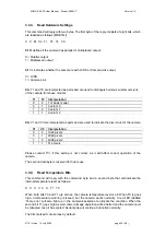
Output mode register (address 208)
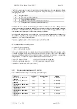
The output mode register is used to change the configuration of data output. Most bits of this
register apply only to Camera Link models. The output mode register will define the pixel
clock frequency, colour order for multiplexed modes, it will enable or disable the shading
correction unit and define which output pins the data is routed to. Also, the serial
communications port can be changed to the desired port from this register.
Function decimal
hexadecimal binary
Outmode
Register
208 D0
1101
0000
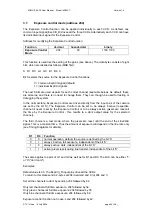
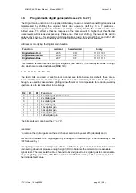
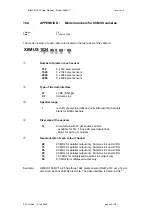
This function is used like the setting of the gains (see above). The data byte consists of eight
bits, which are labelled as follows (MSB first):
SP CL M2 M1 M0 CR X RS
Bit SP selects the frequency of the pixel clock (STRB):
0 = Camera at faster output mode (default)
1 = Camera at slower output mode
Bit SP is defined as Don’t Care (X) for cameras, which do not have two output modes.
Note:
The minimum STRB (PixelStrobe) frequency of the Camera Link standard is 20 MHz.
Possible slower output modes are not guaranteed by the standard.
Bit CL selects the colour output order for multiplexed mode cameras:
0 = RGB colour output (default)
1 = BGR colour output
This bit is Don’t Care for parallel mode cameras.
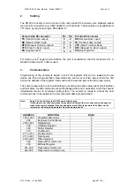
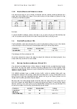
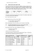
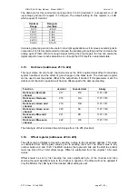
The next three bits M2, M1 and M0 select which ports the data is output to. These bits are
defined differently for multiplexed and parallel mode cameras.
M
2
M
1
M
0
Parallel mode
Connectors
/ ports
Multiplexed mode
Connectors
/ ports
0
0
0 24 bit Base (default)
1 / ABC
8 bit Base (default)
1 / A
0
0
1 24 bit Base + LSB byte
2 / ABCD
10 bit Base
1 / AB
0
1
0 30 bit Medium
2 / ABCEF
12 bit Base
1 / AB
0
1
1 30 bit Dual Base
2 / ABCDE
Reserved
1
0
0 36 bit Medium
2 / ABCEF
Reserved
1
0
1 36 bit Dual Base
2 / ABCDE
Reserved
1 1 0 Reserved
Reserved
1 1 1 Reserved
Reserved
© TVI Vision, 14 July 2006 page 44 ( 56 )

