


21
06
Troubleshooting
Manual 1807 Rev B p/n 001807 0000
LEAK CHECKING TECHNIQUES
If a leak detector is not available, cover suspected
leaks with a low-vapor pressure sealing compound,
such as Apiezon
®
Q, Duct Seal, or Plasticine
®
,
while pumping on the equipment and monitoring
the pressure. A sudden decrease in pressure
indicates that a leak has been covered. Repair
leaks permanently as necessary.
• If the leak is large, causing pressures in the Torr
range, pressurize the process equipment with
1 psig (6.9 kPa) of clean compressed air and
paint a soap solution on suspected leak areas.
Bubbles indicate leaks. De-energize and isolate
the pump during the leak checking. Repair leaks
as required.
• If the leak is small, causing pressures in the sub
Torr range, use a fast-acting thermocouple or
thermistor gauge along with a probing medium
such as helium. Position the vacuum gauge
head downstream from the suspected leak
area, between the leak and the pump. When
the pressure has been reduced so that the
gauge may be used, apply the probing medium
to the suspected leak areas. If the probing fluid
is directed at the leak or an area close to it, a
sudden change in pressure will occur. Cover the
suspected leaks with plastic sealing compound
and continue leak checking until the desired
pressure is obtained.
If leak checking fails, disassemble and remake all
demountable joints and connections using new
gaskets or vacuum sealing compound such as
Loctite 515. Temporary gaskets may be fabricated
from plastic sealing compound, but do not make
them too thick since the material may be squeezed
into the equipment.
OIL CONTAMINATION
If the pressure has been satisfactory for some
time and then gradually increases, this indicates
oil contamination. Clean up the oil by applying gas
ballast, or change the oil as described in
Changing
the Oil on page 14
.
A change in the color of the oil does not necessarily
mean it is unsuitable for use. Conversely, the oil
may be contaminated by vapors yet not change
color.
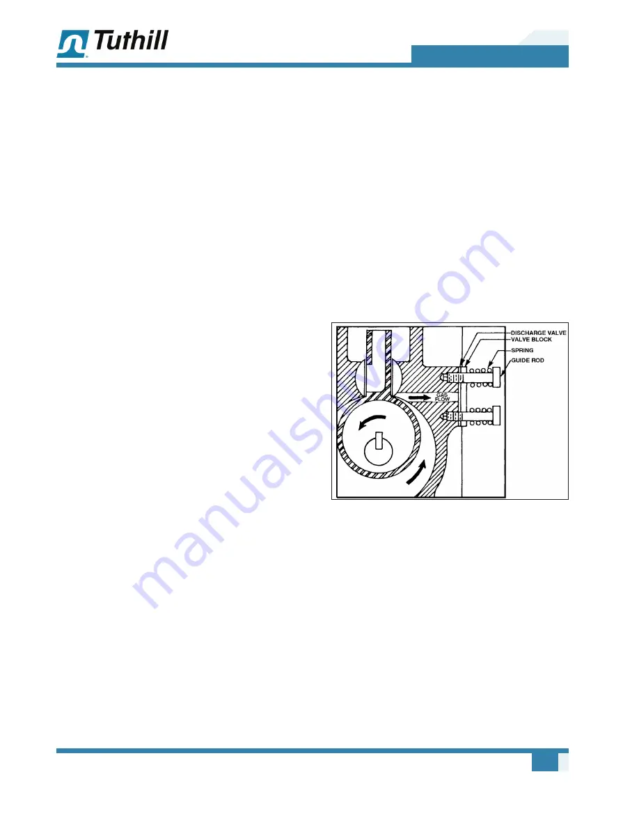
DISCHARGE VALVE
If the cause of poor pump performance was not
due to leaks or oil contamination, then inspect the
discharge valve.
The discharge valve is at the exhaust port of the
backing stage. It should not cause trouble unless
it has mechanical damage or is prevented from
sealing properly due to foreign matter on the valve
seat. When the pump is operating without gas
ballast, a sharp valve noise (a “click”) indicates
proper valve closure.
Figure 6-2 – Discharge Valve Assembly (Typical)
To inspect the discharge valve, proceed as follows:
1. Drain the pump oil by removing both drain
plugs (or by opening the drain valves, if
provided). Remove the cylinder cover to
expose the discharge valve.
2. Remove both guide rods, discharge valve
springs, the discharge valve block, and the
discharge valve. Note how the components
were removed so they can later be replaced
correctly.
3.
Check the discharge valve. It should be flat and
not worn thin on the edges or kinked. The valve
will normally show the outline of the cylinder
Содержание KINNEY KC Series
Страница 6: ...iv Table of Contents Manual 1807 Rev B p n 001807 0000 ...
Страница 17: ...11 Manual 1807 Rev B p n 001807 0000 04 OPERATION Figure 4 1 Pump Components ...
Страница 22: ...16 05 Maintenance Manual 1807 Rev B p n 001807 0000 Figure 5 1 Oil Return Line ...
Страница 34: ...28 08 Reassembly Manual 1807 Rev B p n 001807 0000 ...
Страница 44: ......
Страница 45: ......