19
acetone, alcohol, freon or helium. Position the vacuum gauge head downstream from the suspected
leak area, between the leak and pump. When the pressure has been reduced so that the gauge may be
used , apply probing medium to suspected leak areas using a squirt gun or brush . If the probing fluid
is directed at the leak or an area close to it, a sudden change in pressure will occur. Cover suspected
leaks with plastic sealing compound and continue leak checking until desired pressure is obtained.
4. If leak checking fails, disassemble and remake all demountable joints and connections using new
gaskets or vacuum sealing compound such as Loctite 515. Temporary gaskets maybe fabricated from
plastic sealing compound but these should not be made too thick since the material may be squeezed
into the equipment.
7. MAINTENANCE
7.1 GENERAL
During normal operation, the temperature in the pump will increase in homogeneous manner as a result of
compression work done on the process gas or vapor. It is abnormal if the temperature rise is localized in the
pump and/or the external paint becomes scorched. Localized hot spots are typically due to an inadequate
cooling liquid supply or cooling liquid cut-off, interference of the piston with cams, slide pins, or cylinder, or
because the pump has ingested foreign material, such as solid particulates, metal chips, process material
build up etc. If a localized hot spot is observed, the pump must be shut down immediately for inspection.
Most of pump abnormalities can be noted by routine checks of temperatures, vibration and noise etc. Daily
inspection of the pump is highly recommended as a preventative maintenance. Whenever the pump is
stopped, completely drain the cooling liquid if the pump is located in a cold region or in the winter to prevent
freezing of the cooling liquid.
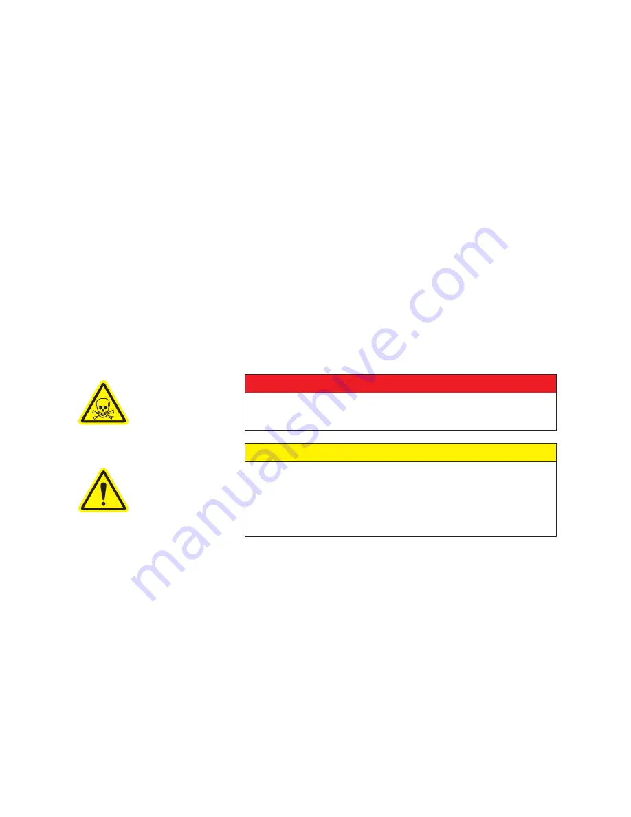
DANGER
The pump and parts may contain hazardous media as determined by the
process. Assure that pump and parts are evacuated of hazardous media
prior to servicing.
CAUTION
The electrical service must be isolated and de-energized prior to
maintenance. Apply appropriate procedures to assure electrical supply is
de-energized and cannot be inadvertently energized during maintenance.
Assure piping and product are isolated prior to maintenance of pump.
Apply appropriate procedures to assure piping and product is isolated and
that inadvertent opening of valves cannot occur during maintenance.
7.2 PERIODIC MAINTENANCE
There is no fixed interval for changing pump oil, since applications vary widely. This can be determined
only by experience and/or by deterioration of pump performance. As a minimum, the pump oil should be
changed after each six month logged period of operation.
At high pressures, or with a gas ballast flow the oil level should be higher than it is when operating at low
pressures near blank off. If there are no changes in the oil level, check for obstructed oil passages. Check
the condition of the oil periodically by draining a small quantity of oil into a clean container and visually
inspecting it for solid or liquid contaminants. Clean strainer after oil pump (KT-500 and KT-850).
7.2.1 CHANGING THE OIL
Run the pump until the oil reaches normal operating temperature 145 to 165°F, (63 to 75°C) and below 100
torr (130 mbar). Stop the pump, place a container under the oil drain valve and open the valve until the oil
is removed from the pump, then close the valve.
Содержание KINNEY 850D
Страница 29: ...29 NOTES ...
Страница 35: ...35 NOTES ...


