5.2.1 User Manual Isoforce
REV 5
01st July 2014
page 1 von 77
TUR Therapietechnik GmbH | Grubenstr. 20 | 18055 Rostock | Germany
Страница 1: ...5 2 1 User Manual Isoforce REV 5 01st July 2014 page 1 von 77 TUR Therapietechnik GmbH Grubenstr 20 18055 Rostock Germany...
Страница 2: ...tely with the authorised supplier of your district Do not attempt any service action by yourselves Isoforce offers remote assistant both for technical as well as for application issues This demands wi...
Страница 3: ...Mode 11 1 3 Contraindications for Resistance Training 12 1 4 Additional Considerations 13 1 5 General Considerations before and after Testing 13 1 6 Safety Considerations 13 Chapter 2 Mechanical Over...
Страница 4: ...Up and Positioning 27 3 1 Ankle 28 3 1 1 PlantarFlexion DorsiFlexion 28 3 1 2 Inversion Eversion 32 3 2 Hip 35 3 2 1 Hip Abduction Adduction Lying on Side 35 3 2 2 Hip Extension Flexion Supine 37 3 2...
Страница 5: ...ing 71 6 1 1 Data Station 71 6 1 2 Adapters 71 6 1 3 Upholstery 71 6 2 Maintenance 71 Chapter 7 Technical Specifications 72 7 1 Laser Pointer 73 7 2 Dynamometer Performance Specifications 73 7 3 Opera...
Страница 6: ...5 2 1 User Manual Isoforce REV 5 01st July 2014 page 6 von 77 TUR Therapietechnik GmbH Grubenstr 20 18055 Rostock Germany Chapter 1 Clinical Considerations...
Страница 7: ...ll As the majority of muscle tears are thought to occur during eccentric motions improvements in this performance may be beneficial for injury prevention However eccentric motions produced by active d...
Страница 8: ...muscular work as a function of time Endurance is the ability of muscles to perform work by holding a maximum contraction for a given length of time or by continuing to move a submaximal load Iso Forc...
Страница 9: ...benefits however are predicated on preventing the accumulation of blood and or edema fluid in the joint or periarticular tissues This is accomplished by the immediate application of a full range of p...
Страница 10: ...imary disadvantage is that the muscular coordination necessary for many types of musculoskeletal activities is not integrated in this exercise which is why isometrics must in time be combined with dyn...
Страница 11: ...centrically and then eccentrically a transient muscle ischemia is produced that compromises blood flow From two to three times more force can be generated with eccentric contractions The clinical impl...
Страница 12: ...proper system of exercise is necessary for the preservation and restoration of muscles after injury However strength building exercises alone would leave much to be desired in developing endurance 1 3...
Страница 13: ...sually apparent until one to two days after treatment Work sub maximally to minimize and develop protocols accordingly The Iso Force is a versatile piece of equipment making it difficult to document e...
Страница 14: ...rt up procedure of the system must be repeated Immediately release the patient in case he she feels uncomfortable by pressing the emergency and removing the straps that keep the adapter in contact wit...
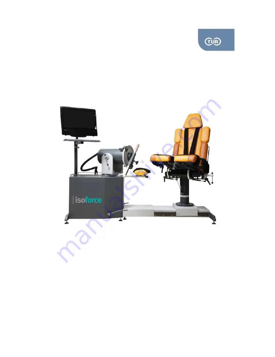
Страница 15: ...5 2 1 User Manual Isoforce REV 5 01st July 2014 page 15 von 77 TUR Therapietechnik GmbH Grubenstr 20 18055 Rostock Germany Chapter 2 Mechanical Overview...
Страница 16: ...l plane both clockwise and counter clockwise In order to do so just lightly step on the dynamometer release pedals DR pedals While pressing them you can rotate the dynamometer either directions On the...
Страница 17: ...The Iso Force system offers the easiest possible way to lift the dynamometer Step on the DR pedals and press the up and down arrows that are placed on the handheld control When pressing the up button...
Страница 18: ...position Also please note that after terminating operator this way the system should be reset 2 1 6 Input Arm Adaptor You can find the input arm adaptor at the front of the dynamometer Attachment and...
Страница 19: ...dle RCH in counter clockwise direction and place the chair in the desired position Firmly tighten the RCH by turning it clockwise There are two RCHs one at each side right under the seat Record the ro...
Страница 20: ...tilt rotate the Seat back Tilt Handle STH counter clockwise Be careful as the seat back returns to the initial position because of the supporting gas spring Hold the back firmly by the support located...
Страница 21: ...ed in the hooks located at the side of the lower seat 2 Thigh Stabilization straps permanently placed on the lower seat 3 Trunk Stabilization belts permanently placed on the back seat To avoid skin ir...
Страница 22: ...5 01st July 2014 page 22 von 77 TUR Therapietechnik GmbH Grubenstr 20 18055 Rostock Germany one of the adapters in the receiving tube turn the knob counter clockwise put the adapter in and secure it...
Страница 23: ...Chair Attachments Adapters Iso Force comes with a set of 16 adapters as standard These can be used either alone or combined Below you can see a list of the available standard adaptors along with the p...
Страница 24: ...1 User Manual Isoforce REV 5 01st July 2014 page 24 von 77 TUR Therapietechnik GmbH Grubenstr 20 18055 Rostock Germany Pic 2 12 ADL5 Pic 2 13 ADS1 Pic 2 14 ADS2 Pic 2 15 ADS3 Pic 2 17 ADT1 Pic 2 16 A...
Страница 25: ...ADL3 Angle attachment used either with knee pad or with antishear knee adapter ADL4 Angle attachment dimensions 555x1155mm Elbow Shoulder Adaptor ADL4 Angle attachment used for ankle patterns ADLS1 S...
Страница 26: ...5 2 1 User Manual Isoforce REV 5 01st July 2014 page 26 von 77 TUR Therapietechnik GmbH Grubenstr 20 18055 Rostock Germany Chapter 3 Set Up Positioning Operation...
Страница 27: ...sed to perform several trials with healthy subjects in order to get familiar with the positioning required for each joint pattern In the Iso Force software you can find additional photos for each posi...
Страница 28: ...re the anterior tibiofibular ligament which connects the tibia to the fibula the lateral collateral ligaments which attach the fibula to the calcaneus and gives the ankle lateral stability and on the...
Страница 29: ...1st July 2014 page 29 von 77 TUR Therapietechnik GmbH Grubenstr 20 18055 Rostock Germany Supine Position Muscles Involved Tibialis anterior posterior toe extensors flexors peroneus tertius triceps sur...
Страница 30: ...l section towards the inside Secure firmly Ask the subject to lay on the chair facing the dynamometer Place the subject s ankle in the ankle adapter and secure it firmly by tightening the straps The s...
Страница 31: ...tachment ADL5 Attach it to the dynamometer by sliding it in the input arm from the top short side Tighten it firmly by turning the knob placed in the input arm clock wise Adjust the chair and the dyna...
Страница 32: ...nd particularly useful for neurological rehabilitation Design a program that comprises of the following sequence Eccentric dorsiflexion heelstrike and eccentric plantarflexion midstance Concentric dor...
Страница 33: ...S4 For modified seated only Set up positioning Put the mechanical stops to B red and B red Attach the ankle ADA1 to the dynamometer by sliding it in the input arm from the top short side Tighten it fi...
Страница 34: ...roximately 55 degrees tilt before you position the subject and position the ADS4 in a way that the subject can put the ankle on the foot plate Set the axis of the joint rotation The axis of rotation g...
Страница 35: ...g of the bones and the strong surrounding ligaments and muscles 3 2 1 Hip Abduction Adduction Lying on Side Rotation Axis Opposite the hip joint 1 cm medially to the anterior superior iliac spine Anat...
Страница 36: ...to make alterations to the positions of the chair and the dynamometer The length of the attachment should be adjusted so that the pad is placed superior to the popliteal fossa Secure the pad by tight...
Страница 37: ...the greater trochanter to the axis of the dynamometer Anatomical Zero Straight leg Range of Motion Extension is blocked due to the pattern position flexion ROM is up to 120 degrees Isoforce offers one...
Страница 38: ...rly on the thigh Secure the pad by tightening the strap Check the axis of rotation by asking your subject to perform flexion of the hip Opposite Side Unstrap patient s thigh from attachment Slide the...
Страница 39: ...tioning Put the mechanical stops to B red and B red Attach the ankle adapter ADA1 to the dynamometer by sliding it in the input arm from the top short side Tighten it firmly by turning the knob placed...
Страница 40: ...e is more likely to be injured than is any other joint in the body 3 3 1 Knee Extension Flexion Rotation Axis Along the long axis of the femur Anatomical Zero Straight leg in neutral position Range of...
Страница 41: ...ect By changing this adjustment you alter the length of the bottom seat Make sure there is a gap between the subject s cuff muscle and the seat Normally a two finger s gap allows a total ROM of 100 de...
Страница 42: ...und Remove the contra lateral adapter from the central receiving tube of the chair and put it the other way around Adjust the chair and the dynamometer to align the subject Follow the steps 6 9 as des...
Страница 43: ...meter To succeed the alignment you might need to make alterations to the positions of the chair and the dynamometer Place the tibia of the subject to the centre of the knee pad You might need to bring...
Страница 44: ...ad ADS4 Set up positioning Put the mechanical stops to B red and B red Attach the ankle ADA1 to the dynamometer by sliding it in the input arm from the top short side Tighten it firmly by turning the...
Страница 45: ...the subject and position the ADS4 in a way that the subject can put the ankle on the foot plate Set the axis of the joint rotation The axis of rotation goes from the machine and extends through the c...
Страница 46: ...ex acting together to provide the nearly full range of motion found in the shoulder the sum of which is greater than the motion available at any single articulation Of the four articulations the glenh...
Страница 47: ...he axis of the joint rotation The axis of rotation for shoulder is through the acromium and it should be right opposite to the colored dot on the input arm of the dynamometer To succeed the alignment...
Страница 48: ...this you can divide the ROM in two and perform two tests instead of one One test could be the external ROM and one the internal Flexion beyond 90 0 produces high variability in results Gravity Correc...
Страница 49: ...iding it in the input arm from the top short side Ask the subject to lay supine on the chair The shoulder to be tested should be on top Subject should face away from the dynamometer Set the axis of th...
Страница 50: ...back turning it around Adjust the chair and the dynamometer in accordance to the quick reference above Follow the steps 6 9 as described above Seated Position Attachments Needed Dynamometer Angle Ada...
Страница 51: ...ide Ask the subject to stop holding the attachment While the subject still lies on the chair slide the chair away from the dynamometer Remove the shoulder attachment from the dynamometer input arm and...
Страница 52: ...is of rotation for shoulder is through the acromiom and it should be right opposite to the coloured dot on the input arm of the dynamometer To succeed the alignment you might need to make alterations...
Страница 53: ...l Zero Mid way between internal and external rotation Range of Motion Different ROMs are normal for the different positioning Possibilities Use the pictures as reference Isoforce offers different posi...
Страница 54: ...n 77 TUR Therapietechnik GmbH Grubenstr 20 18055 Rostock Germany Attachments Needed Dynamometer AAL01 ADW1 and ADS3 Put the mechanical stops to E blue and E red Collect angle elbow attachment and the...
Страница 55: ...input adaptor To succeed the alignment you might need to make alterations to the positions of the chair and the dynamometer Be careful not to lose the 90 abduction angle of the shoulder while trying...
Страница 56: ...e around the wide base known as the capitulum of the humerus There are actually three joints at the elbow The first being the hinge joint formed between the humerus and the ulna called the humeroulnar...
Страница 57: ...ove Attach the adapter to the dynamometer by sliding it in the input arm from the top Ask the subject to lay on the positioning chair or seat on the chair Ask the subject to hold the grip Set the axis...
Страница 58: ...onation Supination Rotation Axis The axis of rotation bisects the head of the ulna distally and the head of the radius proximally Anatomical Zero Thumb pointing upwards Range of Motion Normal ROM is 8...
Страница 59: ...ositioning chair or seat on the chair Ask the subject to hold the grip Set the axis of the joint rotation To achieve the alignment make sure the forearm is parallel to the dynamometer input adaptor To...
Страница 60: ...f the palm extend from the carpus to each of the digits of the hand Each metacarpal is numbered I to V with metacarpal I connecting to the bones of the thumb II connecting to the index finger III conn...
Страница 61: ...us and the muscles that extend the hand at the wrist are the extensor carpi radialis longus extensor carpi radialis brevis and extensor carpi ulnaris Attachments Needed Dynamometer ADL02 ADW1 Chair AD...
Страница 62: ...ubject still lays on the chair slightly rotate the dynamometer to the opposite side Align the dynamometer axis with the joint rotation axis 3 6 2 Radial Ulna Deviation Rotation Axis It is located at t...
Страница 63: ...them as shown in the picture above Combine ADL1 with the ADS4 and put them on the chair input adapter The forearm stabilizer should be at the side of the wrist to be tested Attach the adapter to the d...
Страница 64: ...technik GmbH Grubenstr 20 18055 Rostock Germany Opposite Side Change the direction of the forearm stabilizer While the subject still lays on the chair rotate the dynamometer to the opposite side Align...
Страница 65: ...Dorsi M 33 26 18 12 25 30 Supine knee full extended F 26 20 15 12 Plantar M 126 96 60 41 F 84 64 39 27 Inversion M 31 26 70 Lying F 25 21 Eversion M 25 19 F 18 14 Hip Flexion M 152 126 60 Lying F 91...
Страница 66: ...ed F 8 Extension M 8 F 8 5 Radial M 10 Varying Typical 90 ulnar r adial Seated F 10 Ulnar M 7 6 F 7 6 Shoulder Flexion M 64 59 55 65 Lying F 32 35 31 Extension M 100 83 84 F 49 38 45 Abduction M 53 50...
Страница 67: ...5 2 1 User Manual Isoforce REV 5 01st July 2014 page 67 von 77 TUR Therapietechnik GmbH Grubenstr 20 18055 Rostock Germany Chapter 5 Parameters...
Страница 68: ...ue is achieved Peak torque will usually occur at nearly the same position for similar movements and speeds Coefficient of Variance CV ratio between the standard deviation of a data set our data set pe...
Страница 69: ...y Indicates a muscles ability to perform work over a period of time Important for the rehabilitation of specific activities and is usually compared bilaterally or in pre and post testing Range of Moti...
Страница 70: ...5 2 1 User Manual Isoforce REV 5 01st July 2014 page 70 von 77 TUR Therapietechnik GmbH Grubenstr 20 18055 Rostock Germany Chapter 6 Cleaning and Maintenance...
Страница 71: ...rest of the metal surfaces avoid liquids and use a soft cloth 6 1 3 Upholstery The upholstery should be cleaned and disinfected in accordance to the national regulations for cleaning components that c...
Страница 72: ...5 2 1 User Manual Isoforce REV 5 01st July 2014 page 72 von 77 TUR Therapietechnik GmbH Grubenstr 20 18055 Rostock Germany Chapter 7 Technical Specifications...
Страница 73: ...ic Isokinetic Eccentric CPM Isotonic Isometric Default Maximum Speed for Isokinetic Concentric 500 degrees second Default Maximum Speed for CPM 90 degrees second Default Maximum Speed for Isokinetic E...
Страница 74: ...elative humidity 30 to 75 Atmospheric pressure 700hPa to 1060hPa 7 9 Transport and Storage Conditions Ambient temperature 10 C to 40 C Relative humidity 10 to 95 Atmospheric pressure 500hPa to 1060hPa...
Страница 75: ...5 2 1 User Manual Isoforce REV 5 01st July 2014 page 75 von 77 TUR Therapietechnik GmbH Grubenstr 20 18055 Rostock Germany Chapter 8 Labelling...
Страница 76: ...2 1 User Manual Isoforce REV 5 01st July 2014 page 76 von 77 TUR Therapietechnik GmbH Grubenstr 20 18055 Rostock Germany 8 1 Device Label The label is located at the rear side of the electronic assemb...
Страница 77: ...uses This product conforms with the Directives for medical products 93 42 EWG Conformity Assessment according to MDD 93 42 EEC in cooperation with the notified body MedCert Classification B Accompanyi...