background image

FTE-7000A User's Guide Rev A 5/2014

26

Chapter 7   OTDR Operation

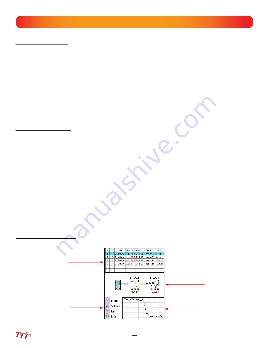
Event Analysis Screen

Fib-R-Map 

Schematic View

Event Table

Event Map

Trace Parameters

Fig  7.10

Sensitivity Settings

There are three levels of sensitivity for the event table and Fib-R-Map.  (See Fig 7.4) To change the event 
sensitivity, press the Menu button, use the left/right buttons to highlight the settings icon and press select.  The 
cursor is the yellow highlighted area. (If the yellow cursor is on a value that is the current selection, that block 
will be highlighted green.)  The setting highlighted in blue is the current setting.  Use the LRUD buttons to 
highlight the desired setting and press select.  To exit the parameter screen, press the menu button.

The lowest setting possible should be used to help 

fi

 lter out any false events that may be caused by short pulse 

widths, but are not true perturbations in the optical signal. High sensitivity presents events with loss down to 
approximately 0.1dB, Medium (Md) with events down to approximately 0.2dB and Low (Lo) for event down to 
about 0.5dB.  Longer pulse widths, and averaging help to lower the number of false events.  Highest sensitivity 
settings should only be used for traces with high signal level, low noise, long pulse width  and long average.  

Macrobend Analysis

Macrobend analysis is performed with the dual trace operation and displayed in the event table.  The traces 
to be compared must have been performed at the same range and the primary trace must be of the longer 
wavelength.  

To conduct a macrobend analysis, open the 

fi

 le manager as described in chapter 9.  Highlight the 

fi

 rst trace to 

be loaded (the trace of the longer wavelength) and select to open.  Open the 

fi

 le manager again and highlight 

the trace to be compared (the trace of the short wavelength), open the drop-down menu under the 

fi

 le tab and  

touch dual or use the up or down buttons to highlight dual and press select.   Open the event analysis screen to 
check for macrobends. If and event on the longer wavelength trace has 0.25db or greater loss than the same 
event on the shorter wavelength trace, a macrobend event will be generated on the event table, identi

fi

 ed by 

a Macro label in the Type column.  This event will immediately follow the event it is related to. For example: 
If event number one was 5 dB at 1550nm and .5 db at 1310nm, the second event will be blank for location, 
+4.5dB for splice, blank for 2point and DB/KM.  The type 

fi

 eld will be listed as Macro.  

To exit dual trace and macrobend analysis, simple start a new scan.

Содержание FTE-7000A

Страница 1: ...e However no responsibility is assumed by Terahertz Technologies Inc for its use nor for any infringements of patents or other rights of third parties that may result from its use No license is grante...

Страница 2: ...een Display 6 3 Power Requirements 6 4 Battery Replacement 7 OTDR Operations 11 7 1 Key Pad 7 2 Entering OTDR Function 7 3 Icon Definitions 7 4 Main OTDR screen 7 5 OTDR Parameter Settings Screen Trac...

Страница 3: ...ximation LSA 7 11 Loss Measurement Settings Setting Basic Splice Loss Measurement Areas Splice Loss Adjustment Areas Splice Loss Adjustment Positions LSA Examples 7 12 Event Analysis Enter Event Analy...

Страница 4: ...anagement Screen File Management Menu File Management File Tab File Management Edit Tab File Management View Help Tab 9 2 File Management Operation Saving a Trace Open View a Trace Dual Trace Delete a...

Страница 5: ...Set 41 11 1 Entering Loss Test Set Function 11 2 LTS File Help Icon Menu Home Quick Save Project Management File Management Help 11 3 Light Source Operation Selecting Light Source Wavelength Selecting...

Страница 6: ...ould cause personal injury Caution A caution alerts to situations that may cause damage to the equipment or produce poor testing condi tions resulting in inaccurate test results Note A special annotat...

Страница 7: ...fiber optic interface of optical test equipment to do so could expose the user to laser radiation and could result in personal injury Warning To Prevent Fire or Shock Hazard Chapter 3 of this manual i...

Страница 8: ...o the unit ensure that all proper cleaning procedures have been followed Use UPC Finish Connectors Only DO NOT insert APC connectors into the optical ports Caution The OTDR is equipped with a protecti...

Страница 9: ...will set the averaging time to 60sec If approximate fiber length is known Set the Wavelength as above and further set the range pulse width and averaging time Press to open the icon menu use the left...

Страница 10: ...a rameters listed and loss and distance measurements displayed The Event tab displays the trace with numbered events and an interactive event table while the Schematic tab displays the trace with num...

Страница 11: ...vailable to answer any questions or provide assistance that you require We at TTI Inc strive to provide premier customer care and technical support by providing timely responsiveness and training We a...

Страница 12: ...USB cable 4 Manual and CertSoft software on CD 5 Set of interchangeable adapters SC ST and FC Fig 5 1 Chapter 5 Inspection and Identification 5 1 Inspection The instrument s Model Part Number Serial...

Страница 13: ...e taken to avoid liquids and contami nants around the fragile optical and electrical connectors and the glass display Use a mild cleaning agent and soft damp cloth to clean up the panels and the outsi...

Страница 14: ...al Time Domain Icon Select this icon to open the OTDR function Firmware Version Touch Screen Tip The home page icons are highlighted by using the left and right buttons pressing the select button will...

Страница 15: ...low these caution statements could cause unsafe conditions for the operator and equipment and may void the warranty 6 4 Battery Replacement To replace the batteries remove the OTDR from the protective...

Страница 16: ...he project folder and file manager it opens the file edit menu bar When the menu is displayed at the top of the screen the focus of the LRUD buttons and the select buttons are on the icon menu and no...

Страница 17: ...ysis view Settings Opens the parameters setting page Splice Zone Setting Turns on LSA Splice markers Help Opens the context sensitive help menu Lambda Wavelength Cycles through available wavelengths P...

Страница 18: ...in this area to cycle through the loss methods Test Parameters Displays test parameters of wave length averaging time pulse width range and ORL Touch the symbol or value to cycle through the avail abl...

Страница 19: ...touch screen To change parameters or event sensitivity simply touch the desired value To set thresholds and time touch the setting and the block will show yellow The digits may now be adjusted with th...

Страница 20: ...o highlight the calendar month and press select Use the left and right buttons to change the month and press select Use the LRUD buttons highlight the date and press select Use the LRUD to buttons to...

Страница 21: ...the menu button to display the menu at the top of the display Use the LRUD buttons to highlight the Lambda Wavelength icon press select to cycle through the available wavelengths and press the menu bu...

Страница 22: ...IOR Icon Press select and the IOR for the wavelength that is the active will be displayed To change the IOR use the on screen QWERTY keyboard to enter the new value and touch save Each wavelength sto...

Страница 23: ...tes Scan Once all the proper settings have been entered press the Scan button to take the trace To stop the trace press the scan button again Chapter 7 OTDR Operation Range 5ns 10ns 30ns 100ns 300ns 1...

Страница 24: ...will be save in numeric order For example if the base file name of romecity were entered the first test in construction mode If the test were at 1310 1550nm would be a test at 1310nm with a name of ro...

Страница 25: ...dual trace mode When the test is complete for the first fiber remove the connector from the OTDR insert the next fiber to be tested and press the scan button Continue until all test are complete Note...

Страница 26: ...cursor The cursors are moved using the left and right buttons 7 9 Loss Measurements 2 Point loss 2 Point loss measurements take into account the difference in vertical height between where the A and...

Страница 27: ...ss It is necessary to set these areas in clear backscatter areas that do not consist of other events to acquire the most accurate measurements For accurate measurements these areas can not include oth...

Страница 28: ...ition 3 Splice Loss Position 2 LSA Splice Loss Measurement Areas LSA Splice Loss Measurements Fig 7 5 Basic Splice Loss Measurements Basic Splice Loss Measurement Areas Active Splice Zone Cursor Activ...

Страница 29: ...erly Fig 7 7 The LSA area and cursor are set too late The left most green LSA indicator line is not over laying the back scatter of the trace Fig 7 8 The LSA area and cursor are set properly The green...

Страница 30: ...ellow highlighted area If the yellow cursor is on a value that is the current selection that block will be highlighted green The setting highlighted in blue is the current setting Use the LRUD buttons...

Страница 31: ...ettings should only be used for traces with high signal level low noise long pulse width and long average Macrobend Analysis Macrobend analysis is performed with the dual trace operation and displayed...

Страница 32: ...alue Fig 7 12 Chapter 7 OTDR Operation System ORL Link Data Note The Link is the last item in the schematic view It is labeled E in the event number position The loss value just prior to this item is...

Страница 33: ...old for the Pass Fail feature The E event will display LINK as this is not an event that would have meaning The event that is deemed the EOF will normally display a large loss as this loss will be gre...

Страница 34: ...menu press the menu button There are four tabs available File Edit View and Help Use the left or right buttons to move to a desired tab and use the select or the down button to open the drop down menu...

Страница 35: ...ct to move to the file management page For onboard help pages highlight the help tab and press select Fig 8 5 Fig 8 4 Project Management File Tab To open the drop down menu under file with file tab hi...

Страница 36: ...reen press menu press select use the down button to highlight exit and press select again Open an Existing Project To open a project press the menu button highlight the project folder and press select...

Страница 37: ...meters Test parameters may be temporarily changed by selecting new settings such as wavelength average time pulse width and range directly on the main OTDR screen with the touch screen capabilities or...

Страница 38: ...Any files saved in the scope function will also be associated with the open folder Fig 9 1 File Management File Menu The menu for file management may be operated with the touch screen however this man...

Страница 39: ...oftware Rename allows the highlighted file name to be modified Properties is grayed out and not accessible from this location File Management View and Help Menu View offers the user the opportunity to...

Страница 40: ...b press select or the down button to open the drop down menu Use the down button to highlight Exit and press select Open View a Trace To open a trace press the menu button highlight the file folder an...

Страница 41: ...nagement and Help Home Press the menu button use the left and right buttons to highlight the home icon and press select to return to the home Screen Fig 10 1 10 2 Video Scope Display Touch Screen Tip...

Страница 42: ...types are identified by a preceding icon Trace files are indicated by a trace icon LTS file by an LTS icon and scope files are preceded by scope target icon Help Press the menu button use the left and...

Страница 43: ...d pull the tip straight up from the probe To place a tip on the probe ensure the lens is clean slide the tip on to the end of the probe and tighten the tip retention nut Do not overtighten the retenti...

Страница 44: ...us has be marked the scan may be paused with the scan button and the points of contamination that caused a failure may be marked on the image Marking Points of Contamination To mark the points of cont...

Страница 45: ...wable Scratches Width Allowable Defects Diameter A Critical Zone 0 m to 25 m None None B Cladding Zone 25 m to 120 m No limit 3 m None 3 m No Limit 2 m 5 from 2 m to 5 m None 5 m C Adhesive Zone 120 m...

Страница 46: ...ull description of project management operation please refer to Chapter 9 of this user s guide Help Press the menu button use the left and right buttons to highlight the help icon and press select to...

Страница 47: ...d exactly as entered using this method To have the files saved with incremen tally number suffixes use the file manager to save the base file name with the suffix number as the first file to be save i...

Страница 48: ...W x 1 57 H 205mm L x 99mm W x 40mm H Weight 1 6 lbs Communications ports USB Connector Styles FC ST or SC Interchangeable TTI reserves the right to change specifications without notice Fiber Type Sing...

Страница 49: ...nted to be free of defects in workmanship and material for a period of one 1 year from the date of delivery This warranty does not apply to expendable parts such as batteries or optical panel connecto...

Страница 50: ...llows OTDR V1 0 0 0 02 2014 Original release V1 1 0 4 05 2014 Event table and schematic access from OTDR screen via tabs Event marker overlay on trace graph when in either event or schematic tab Redes...

Отзывы: