background image

TTP-245C/ TTP-343C/ TTP-244CE 
Bar Code Printer Service Manual 


21 


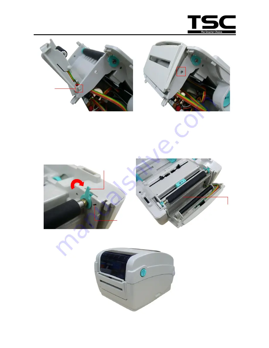
5. Then, put back the lower inner cover. 

6. Close the top cover and then upside down the printer. 

7. Fasten the 6 screws at the lower inner cover. 

8. Open the peel-off cover. Disengage one of platen holder tab from lower inner cover and 

rotate the tab 90 degrees to install the peel-off bar into the both slots. Then, rotate the tab 

90 degrees to engage the platen holder tab to the lower inner cover.


9. Place the printer in the flat and secured desktop for media loading and printing. 


Tenon 

Slot 

Tab 

Peel-off bar 

Содержание TTP-244CE series

Страница 1: ...TTP 245C TTP 343C TTP 244CE SERVICE MANUAL THERMAL TRANSFER DIRECT THERMAL BAR CODE PRINTER ...

Страница 2: ...Cover and Media View Window Cover 11 3 2 Replacing the Lower Cover 13 3 3 Replacing the Main Board 14 3 4 Replacing the Platen Roller Assembly 15 3 5 Replacing the Print Head Assembly 16 3 6 Replacing the Stepping Motor 18 3 7 Replacing the Feed Button and Feed Button PCB 19 3 8 Peel off Module Installation Option 20 3 9 Cutter Module Installation Option 22 4 TROUBLESHOOTING 24 4 1 LED Status 24 4...

Страница 3: ...D card spec SD card capacity Approved SD card manufacturer V1 0 V1 1 128 MB SanDisk Transcend V1 0 V1 1 256 MB SanDisk Transcend Panasonic V1 0 V1 1 512 MB SanDisk Transcend Panasonic V1 0 V1 1 1 GB SanDisk Transcend Panasonic V2 0 SDHC CLASS 4 4 GB V2 0 SDHC CLASS 6 4 GB SanDisk Transcend Panasonic V1 0 V1 1 microSD 128 MB Transcend Panasonic V1 0 V1 1 microSD 256 MB Transcend Panasonic V1 0 V1 1...

Страница 4: ... MB Transcend Panasonic V1 0 V1 1 miniSD 256 MB Transcend Panasonic V1 0 V1 1 miniSD 512 MB Transcend Panasonic V1 0 V1 1 miniSD 1 GB Transcend Panasonic V2 0 SDHC CLASS 4 miniSD 4 GB Transcend V2 0 SDHC CLASS 6 miniSD 4 GB The DOS FAT file system is supported for the SD card Folders files stored in the SD card should be in the 8 3 filename format The miniSD microSD card to SD card slot adapter is...

Страница 5: ...w 1 Ribbon rewind hub 2 Ribbon rewind gear 3 Gap sensor receiver 4 Media holder 5 Media holder lock switch 6 Gap sensor transmitter 7 Printhead 8 Ribbon supply hub 9 Top cover support 10 Media guide adjustment knob 11 Black mark sensor 12 Platen roller 9 11 10 5 4 3 8 7 1 2 12 6 ...

Страница 6: ...3C TTP 244CE Bar Code Printer Service Manual 1 3 Rear View 1 Ethernet interface 2 USB interface 3 Centronics interface 4 RS 232C interface 5 Power jack socket 6 Power switch 7 Fan fold paper entrance chute 1 3 5 4 2 6 7 ...

Страница 7: ... of Board Connectors Main board Connector Description Remark 1 Power switch SW1 2 Power supply output 24V DC connector B1 3 RS 232C connector JP7 4 Centronics port connector JP4 5 USB connector JP9 6 Ethernet connector JP3 7 1 7 2 1 2 3 4 5 6 8 9 10 11 12 13 14 15 16 17 18 19 20 21 22 23 ...

Страница 8: ...r AD 1 5 2 8V 2 GND 0V 14 Stepping motor connector JP14 15 Cutter connector JP35 Pin Description Voltage 1 Cutter power 24V 2 GND 0V 3 Cutter direction 0V Cutter positive cut 5V Cutter negative cut 4 Cutter enable 0V Cutter work 5V Cutter stop 5 Cutter position sensor switch 0V Cutter stop 3 3V Cutter work 6 GND 0V 7 Logic power 5V 8 Reserved 16 Feed key and LED connector JP28 Pin Description Volt...

Страница 9: ... 7 3 3V Head open 3 GND 0V 19 Gap sensor emitter connector JP29 Pin Description Voltage 1 Power 3 3V 2 Gap sensor emitter Emitter on 2 1 2 3V Emitter off 2 6 2 8V 20 Black mark sensor connector JP17 Pin Description Voltage 1 Not use 2 Power 3 3V 3 Black mark sensor emitter Emitter on 2 1 2 3V Emitter off 2 6 2 8V 4 Black mark sensor receiver AD 0 3 3V 5 Power 3 3V 21 Gap sensor receiver connector ...

Страница 10: ...TTP 245C TTP 343C TTP 244CE Bar Code Printer Service Manual 8 Main board bottom Connector Description Remark 1 Firmware recover card connector JP37 1 ...

Страница 11: ...ine indicates that there are valid data at the host When this pin is de asserted the ve clock edge should be used to shift the data into the device 2 9 Data 0 7 N A In Data Bus Single directional 10 Ack N A Out A low on this line indicates that there are valid data at the Device When this pin is de asserted the ve clock edge should be used to shift the data into the host 11 Busy N A Out When in re...

Страница 12: ...Out Extensibility flag 14 Ground N A GND Ground 15 No Defined N A N A 16 17 Ground N A GND Ground 18 No Defined N A N A 19 30 Ground N A GND Ground 31 No Defined N A N A 32 Error Fault N A Out A low set by the device indicates that the reverse data is available 33 35 Ground N A GND Ground 36 No Defined N A N A Ethernet PIN CONFIGURATION 1 Tx 2 Tx 3 Rx 4 N C 5 N C 6 Rx 7 N C 8 N C ...

Страница 13: ...and use the Phillips screwdriver to remove the 4 screws from hinge holder 2 Open the printer top cover by pulling the top cover open lever located on each side towards the front of the printer then lift the top cover to the maximum open angle 3 Use the Phillips screwdriver to remove the 6 screws from the top inner cover 4 Use the slotted screwdriver to remove the 2 screws that hold the print head ...

Страница 14: ...e Printer Service Manual 12 5 Disconnect the harness from the feed button PC board 6 Remove Replace the top cover and media view window cover 7 Reassemble the parts in the reverse procedure Screws Screws Media view window cover Top cover ...

Страница 15: ... Printer Service Manual 13 3 2 Replacing the Lower Cover 1 Turn the printer upside down and use the Phillips screwdriver to remove the 6 screws 2 Remove Replace the lower cover 3 Reassemble the parts in the reverse procedure Screws Screws ...

Страница 16: ...1 screw from the main board 3 Disconnect all connectors from the main board 4 Use the Phillips screwdriver to remove the 2 screws and use socket wrench to remove the 2 bolts 5 Then take off the interface plate and black Mylar Remove Replace the main board 6 Reassemble the parts in the reverse procedures Main board Screws Bolts Screws Interface plate ...

Страница 17: ... front of the printer then lift the top cover to the maximum open angle 2 Disengage the platen holder tabs to the lower inner cover by pulling out the right side and left side tabs toward the center of platen and rotates 90 degrees 4 Take out the platen roller assembly and replace a new platen roller assembly 5 Reassemble the parts in the reverse procedures Platen roller assembly Tab Unhook ...

Страница 18: ...o the maximum open angle Open the ribbon access cover 2 Use the slotted screwdriver to remove the 2 screws that hold the print head bracket Let print head bracket drops into its place 3 Use the slotted screwdriver to remove 2 screws that fix the print head spring plate 4 Pull the print head module forward to take out the module and disconnect the print head harness Replace the print head assembly ...

Страница 19: ...t head module spring plate into the ribbon base print head spring plate slot Note There is static brush adhered on the print head spring plate The static brush free end side is toward the paper feed direction 7 Make sure the TPH bracket hinge slots are engaged with the hinges at both sides 8 Reassemble the parts in the reverse procedures Print head harness cover ...

Страница 20: ...ing motor you will see the plastic parts for mounting the stepping motor and thermister 5 Remove Replace the stepping motor Note Make sure the stepping motor is mounted at the correct location and thermistor is applied with the thermal conductive grease to keep good contact with stepping motor case 6 Reassemble the parts in the reverse procedures Stepping motor connector Screws Stepping motor 203 ...

Страница 21: ... Feed Button and Feed Button PCB 1 Refer to section 3 1 to remove the top cover 2 Remove the screws that fixe the feed PCB to the mechanism 3 Remove Replace the feed button and feed PCB 4 Reassemble the parts in the reverse procedures Screws Feed PCB Top cover Feed PCB Feed button ...

Страница 22: ...ll up the front panel from the printer Thread the 5 pin peel off module harness through the front slot of lower inner cover 3 Plug in the peel off module harness connector to the 5 pin red socket on the main board 4 Embed the tenons into the both sides mortise of lower inner cover and close the peel off cover Front panel Peel off module harness Slot 5 pin socket Peel off module ...

Страница 23: ...the lower inner cover 8 Open the peel off cover Disengage one of platen holder tab from lower inner cover and rotate the tab 90 degrees to install the peel off bar into the both slots Then rotate the tab 90 degrees to engage the platen holder tab to the lower inner cover 9 Place the printer in the flat and secured desktop for media loading and printing Tenon Slot Tab Peel off bar ...

Страница 24: ... 2 to remove the lower cover 2 Open the top cover and pull up the front panel from the printer 3 Thread the cutter module 8 pin harness through the front slot of lower inner cover 4 Connect the cutter module harness connector to the 8 pin white socket on the printer main board Harness of the cutter module Slot Front panel ...

Страница 25: ...into the both sides notches of lower inner cover as picture below then push cutter to lock into the lower inner cover 7 Close the top cover and then upside down the printer 8 Fasten the 6 screws at the lower inner cover 9 Place the printer in the flat and secured desktop for media loading and printing 8 pin socket Cutter module ...

Страница 26: ...pply is broken Check both power connections from the power cord to the power supply and from the power supply to the printer power jack if they are connected securely Solid Green ON The printer is ready to use No action necessary Green with blinking Pause The printer is paused Press the FEED button to resume for printing Red with blinking Error The out of label or ribbon or the printer setting is ...

Страница 27: ... Follow the instructions in loading the media or loading the ribbon Ribbon run out Loading the ribbon Continuous feeding labels The printer setting may go wrong Please do the initialization and gap black mark calibration Paper Jam Gap black mark sensor sensitivity is not set properly sensor sensitivity is not enough Calibrate the gap black mark sensor Make sure label size is set properly Set label...

Страница 28: ...vice Manual 26 Check if print density is set properly Adjust the print density and print speed Check print head test pattern if head element is damaged Run printer self test and check the print head test pattern if there is dot missing in the pattern ...

Страница 29: ...thod Interval Print Head 1 Always turn off the printer before cleaning the print head 2 Allow the print head to cool for a minimum of one minute 3 Use a cotton swab Head cleaner pen and 100 ethanol to clean the print head surface Clean the print head when changing a new label roll Platen Roller 1 Turn the power off 2 Rotate the platen roller and wipe it thoroughly with 100 ethanol and a cotton swa...

Страница 30: ...the print head and supply sensors once change a new ribbon to keep printer performance and extend printer life Continuous printing will cause printer motor overheat Printer will stop printing automatically about 10 15 minutes until motor is cooling down Please don t turn off power when printer pauses or the data transfered to printer buffer will be lost The maximum printing ratio per dot line is 1...

Страница 31: ...amille 2009 2 17 Add peel off module installation section Camille 2009 3 16 Modify section 1 1 Recommended SD card specification Camille 2009 8 21 Modify section 3 8 Peel off module installation Camille 2009 9 30 Modify section 2 1 Camille 2010 11 3 Modify section 3 1 Camille 2011 1 25 Modify TSC address Camille 2011 4 7 Modify section 2 2 Camille ...

Страница 32: ......

Страница 33: ...st Rd Wujie Township New Taipei City 23141 Taiwan R O C Yilan County 26841 Taiwan R O C TEL 886 2 2218 6789 TEL 886 3 990 6677 FAX 886 2 2218 5678 FAX 886 3 990 5577 Web site www tscprinters com E mail printer_sales tscprinters com tech_support tscprinters com TSC Auto ID Technology Co Ltd ...

Отзывы: