background image

126 


Cleaning Procedure 


Cleaning Procedure of Printhead Face 

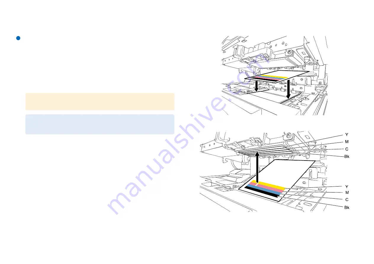
Execute this cleaning in the case white streak can not be recovered by Strong Cleaning.


1)


Print Nozzle Check Pattern using Service Utility. 


Service Utility > Test Print/Adjustment > Nozzle Check pattern 

2)


Move Printhead to head cleaning position (*1) using Service Utility. 


Service Utility > Troubleshooting > Position Change > Head Cleaning Position 

*1 Head cleaning position is same as printing position. 


3)


Open Upper Unit. 


4)


Set printed Nozzle Check Pattern on print paper. 


5)


Find white streak on printed paper, and then find non-firing nozzle.


CAUTION: 

Do not keep Printhead at head cleaning position for a long time.


NOTE: 
It takes 5 seconds to move Printhead to head cleaning position. 

Содержание CPX4P Series

Страница 1: ...CPX4P Service Manual COLOR INKJET LABEL PRINTER ...

Страница 2: ...typographical errors due to improvements or changes in products When changes occur in applicable products or in the contents of this manual technical information will be released as the need arises The following paragraph does not apply to any countries where such provisions are inconsistent with local law Trademarks The product names and company names used in this manual are the registered tradem...

Страница 3: ...switch closing the front door and closing the delivery unit door which results in supplying the machine with power 2 In the digital circuits 1 is used to indicate that the voltage level of a given signal is High while 0 is used to indicate Low The voltage value however differs from circuit to circuit In addition the asterisk as in DRMD indicates that the DRMD signal goes on when 0 In practically a...

Страница 4: ...onent Names 8 Front View 8 Rear View 8 Internal View Front 9 Internal View Rear 9 Front Cross sectional View 10 Horizontal Cross sectional View 10 Operation Panel 11 2 Technology 12 Basic Configuration 12 Functional Configuration 12 Outline of Electrical Circuits 14 Drive Configuration 15 Basic Sequence 16 Power Supply 19 Image Formation System 20 Image Formation System 20 Control 21 Ink Supply Sy...

Страница 5: ... Replacing Printhead 93 Removing Purge Unit 97 Removing Tube 98 Removing Transport Unit 99 PCB 102 Removing Needle Unit Ink Tank Relay PCB 102 Removing Operation Panel PCB 103 Removing Printer Controller PCB 104 Removing DC Power Supply PCB 106 Removing Maintenance Cartridge Relay PCB 109 Removing Printhead Relay PCB 110 Motors 111 Removing Roll Motor 111 Removing Transport Motor 112 Removing Valv...

Страница 6: ...ng Before Installation 196 Checking the Power Supply 196 Checking the Installation Environment 196 Checking the Installation Space 197 Installation Precautions 197 Checking the Contents 198 Unpacking Procedure 199 Installation Procedure 202 Mounting Printhead Unit 202 Loading Ink Tanks 208 Installing Cutter Unit 210 Initial Ink Loading 210 Checking after Installation 211 Setting of Test Label 211 ...

Страница 7: ...3 ...

Страница 8: ... shall be disconnected to de energize the phase conductors German VORSICHT Die Sicherung kann sich im Nullleiter befinden und das Hauptnetz muss abgetrennt werden um die Phasenleiter stromlos zu machen Wenn mit dem falschen Typ ausgewechselt besteht Explosionsgefahr Gebrauchte Batterien gemäß der Anleitung beseitigen 如果更換不正確之電池型式會有爆炸的風險 請依製造商說明處理用過的電池 For CA USA Only Included battery contains Perc...

Страница 9: ...aximum printing speed of 150 mm sec at 1200 dpi for vertical scanning by 1200 dpi for horizontal scanning Compact Space Saving Light Weight Compact space saving design makes for printer weight of Approx 24Kg 53 lbs When packed approx 31Kg 69 Ibs AIS Auto Image Shifter AIS function which shifts printed images for each set of 10 000 sheets realizes longer lives of Printheads Non Ink Recycling Non in...

Страница 10: ...e to complete printing of first page after pressing print button 10 seconds or less 3 4 3 4 3 in label 4 CPU Intel Core 2 Quad Q6700 2 66 GHz Memory 3 GB HDD 80 GB OS Windows XP SP2 I F Hi Speed USB External dimensions W D H 386 x 570 x 394 mm 15 2 x 22 4 x 15 5 in When Cutter is installed 386 x 687 x 394 mm 15 2 x 27 0 x 15 5 in Weight Approx 24 kg Approx 53 lbs 5 6 5 Excluding Printheads and Ink...

Страница 11: ...umption 250W Printer only 265W Reference value with optional cutter Average power consumption Power ON 25 W or less Sleep mode 9 W or less Cleaning Item Specifications Cleaning types Maintenance jet cleaning wipe cleaning and tube pump type suction cleaning Cleaning mode Automatic cleaning At power ON when Printer backs from sleep mode before printing during printing after printing etc Manual clea...

Страница 12: ...er 2 Operation Panel 7 Roll Cover 3 Ink Tank Door 8 Rear Cover 4 Cutter Cover 9 Maintenance Cartridge Door 5 Maintenance Cover Rear View 1 Rear Feeder Slot 5 USB Connector 2 Power Socket 6 LAN Connector 3 RS 232C Connector 7 Left Cover 4 RS 232C Connector ...

Страница 13: ...9 Internal View Front 1 Ink Tank Lever 2 Transport Unit 3 Roll Holder Internal View Rear 1 Pinch Roller Release Lever 4 Paper Guide 2 Maintenance Cartridge 5 Upper Unit Open Lever 3 Transport Guide ...

Страница 14: ... Ink Tan 4 Printhead 9 Black Ink Tan 5 Purge Unit Horizontal Cross sectional View 1 Transport Sensor 7 DC Power Supply PCB Unit 2 Printhead 8 Paper Suction Fan 3 Upper TOF Sensor PCB 9 Lower TOF Sensor PCB 4 Roll Holder 10 Transport Belt 5 Printer Controller PCB 11 Purge Unit 6 Maintenance Cartridge 12 Transport Sensor Flag ...

Страница 15: ...11 Operation Panel 1 Power Key 2 PAUSE Key 3 FEED Key 4 BACK FEED Key 5 Ink Warning Lamp 6 Maintenance Cartridge Lamp 7 ERROR Lamp 8 STATUS Lamp ...

Страница 16: ...n the print data to form a print image on paper It consists of Printheads Printhead Lifter Part and Purge Unit in Print Module 1 Printhead Lifter Part 2 Purge Unit Ink Supply System Ink Supply System supplies ink from Ink Tank to Printheads suctions ink from Printheads and collects waste ink from Purge Unit to Maintenance Cartridge It consists of Ink Tank Holder Unit Valve Unit and Pump Unit in Pr...

Страница 17: ...13 Feeder Transport System Feeder Transport System feeds paper It consists of Roll Drive Unit Paper Guide Unit and Transport Unit 1 Roll Drive Unit 2 Transport Unit 3 Paper Guide Unit ...

Страница 18: ...computer and ASIC It performs image processing for print data and performs all kinds of control related to Printheads It has Flash ROM to allow to rewrite software using a PC Image data management Control of motors solenoids clutches sensors fans and switches Management of temperature and humidity data Control of DC Power Supply PCB output Command data analysis Overlay data retention Communication...

Страница 19: ...15 Drive Configuration M103 Purge Motor CL101 Valve Clutch M104 Printhead Lift Motor CL102 Pump Clutch M105 Pump Motor SL101 Buffer Solenoid M101 Roll Motor M102 Transport Motor M106 Valve Motor ...

Страница 20: ... printing properly is broadly classified into hardware start and initialization sequences On the other hand shutdown processing is performed at power off to retain Printer condition normally until Printer is used next time Hardware Start Sequence This is electrical initialization performed when Printer is turned on ...

Страница 21: ...onversion 6 Sensor monitoring start Starts monitoring of the sensors used to detect open closed states of various Covers and presence absence of ink 7 EEPROM check Checks the data stored in EEPROMs mounted on Printheads and Ink Tank 8 Printhead AD conversion start Starts AD conversion of Printhead temperature 9 Temperature monitoring start Starts monitoring of a Printhead temperature error 10 Prin...

Страница 22: ...ce Cartridge 5 NVRAM SAVE Saves various data in Flash ROM 6 Printhead temperature monitoring stop Stops controlling detection of a Printhead temperature error 7 Printhead AD conversion stop Stops AD conversion of Printhead temperature 8 AD conversion stop Stops obtaining AD conversion values of paper width internal temperature humidity Printhead temperature and TOF Sensor 9 Sensor monitoring stop ...

Страница 23: ...re supplied like the illustration below Printer has sleep mode DC 5V supply all the time while power is turned on DC 24V output is controlled by PWRON signal of Printer Controller PCB PWRON signal is changed H and L related to the operation of Power Key on Operation Panel and signal from printer driver of PC ...

Страница 24: ...System discharges ink from Printhead based on the print data to form a print image on paper It consists mainly of Printheads Printhead Lifter Part and Purge Unit in Print Module The basic configuration of Image Formation System is shown below 1 Printhead 2 Printhead Lifter Part 3 Purge Unit ...

Страница 25: ... are also performed at the capping position along with driving of Pump Unit Evacuation Position Home Position Whenever Printhead Lifter Part moves it moves up to the evaluation position temporarily Printhead Lifter Part temporarily moves to the position where it is detected by Printhead HP Sensor P105 and then moves to the predetermined position according to the predetermined number of drive pulse...

Страница 26: ...printing Printheads Overview Printheads of Printer have 5 184 Ink Discharge Nozzles which are arranged on very small Heater 5 124 nozzles are used for actual printing and the remaining 60 nozzles are used for sideways registration Ink supplied from Ink Tank is filtered and supplied to Nozzles When Printhead drive current flows to Nozzle Heater ink drops from Nozzles due to the bubbles generated fr...

Страница 27: ...Never replace Printhead with it placed in any place other than the Printhead Replace Tool Poor printing can result 1 Shaft 3 Nut 2 Spacer 4 Printhead replacement jig AIS Auto Image Shift Function AIS function shifts whole images by 16 dots for each set of 10 000 sheets printed to extend Printhead life for printing ruled line images continuously Useful on images involving ruled lines up to 0 32 mm ...

Страница 28: ...t is driven by Purge Motor M103 The home position of Purge Unit is detected by Purge Position Sensor Movement from the home position to the predetermined position is controlled according to the number of drive pulses of Purge Motor M103 a Home position Evacuation position Reference position to which Printheads are evacuated when Printhead Lifter Part moves to the predetermined position or when Pur...

Страница 29: ...p 6 Timing Belt Outline of Operation Purge Unit performs maintenance for Nozzles of Printheads to maintain print quality Purge Unit has capping and cleaning functions Purge Unit protects the Printhead faces from drying and dust collects maintenance jet ink drives Pump Unit and performs cleaning 1 Purge Unit Performs maintenance of Nozzles of Printheads 2 Purge Position Sensor P106 Detects the home...

Страница 30: ...scharges occur Yes Yes 9 Medium Cleaning Cleaning somewhat stronger than Light Cleaning when non discharges persist after Light Cleaning Yes Yes 10 Strong Cleaning Cleaning somewhat stronger than Medium Cleaning when non discharges persist after Medium Cleaning Yes Yes Yes 11 Flushing Cleaning This cleaning is carried out when faded area is seen in solid image Yes 12 Initial ink loading Loads ink ...

Страница 31: ...ion has been performed or maintenance jet counter for determining whether cap suction has been executed has reached the specified value after completion of each recovery operation Cleaning of initialization Detect that fifty five days passed since the last time for ink stirring Detect that sixty days passed since the last time for ink stirring Detect that eighty five days passed since the last tim...

Страница 32: ...erated for 180 seconds for ink level adjustment or the state in which the pressure change amount is 2 kPa has been held for 90 seconds Only this cleaning is executed at occurrence of an error not after recovery of the error occurrence of the error is not reported Cleaning after error recovery Printer state Cleaning name After error recovery Atmosphere slot suction execution judgment counter has re...

Страница 33: ...k to Printheads suctions ink from Printheads and collects ink from Purge Unit into Maintenance Cartridge It consists of Ink Tank Holder Unit Valve Unit and Pump Unit in Print Module The basic configuration of Ink Supply System is shown below 1 Ink Tank Holder Unit 3 Valve Unit 2 Pump Unit 4 Ink Tank ...

Страница 34: ...d they are opened and closed through rotation of cams in the order of Bk C M Y Buffer Valve Buffer Valve is provided at the buffer section chamber of Pump Unit and it is opened and closed through driving of solenoid Pressure Release Valve Pressure Release Valves corresponding to individual colors are provided at the base plate to which Purge Unit is mounted and they are opened and closed at the sa...

Страница 35: ... mode Open Closed state of each Valve Suction Pump Between Printheads and Caps Bubble removing Valve Ink Supply Valve Suction Valve Pressure Release Valve Buffer Valve Wipe Valve Initial ink loading Ink supply from Ink Tanks to Sub Tanks Open Closed Closed Open Closed Open Driven Sealed Collection of shipping ink 1 Reduction of pressure in Buffer Closed Closed Closed Open Closed Open Driven Sealed...

Страница 36: ...on and Sub Tank and the ink passage between Sub Tank and Ink Tank Thus feeding ink to Sub Tank When the predetermined amount of ink is poured in Sub Tank Bubble Removing Valve is closed Air flows into Ink Tank through Hollow Needle atmosphere side thus maintaining the pressure in Ink Tank constant This operation is performed for individual colors in order Bk C M Y Open closed states of valves the ...

Страница 37: ...ion state of Suction Pump and the capping state of Printhead are shown below 1 2 3 4 5 6 7 Bubble Removing Valve Ink Supply Valve Suction Valve Air Release Valve Buffer Valve Wipe Valve Suction Pump Between Printhed and Cap Open Closed Closed Open Closed Open Driven Sealed A schematic diagram of ink passages is shown below 8 Pump Unit 12 Purge Unit capping position 9 Buffer 13 Maintenance Cartridg...

Страница 38: ...fer via Cap Open closed states of valves the operation state of Suction Pump and the capping state of Printhead are shown below 1 2 3 4 5 6 7 Bubble Removing Valve Ink Supply Valve Suction Valve Air Release Valve Buffer Valve Wipe Valve Suction Pump Between Printhed and Cap Closed Closed Open Closed Closed Open Driven Sealed A schematic diagram of ink passages is shown below 8 Pump Unit 12 Purge U...

Страница 39: ... state of Suction Pump and the capping state of Printhead are shown below 1 2 3 4 5 6 7 Bubble Removing Valve Ink Supply Valve Suction Valve Air Release Valve Buffer Valve Wipe Valve Suction Pump Between Printhed and Cap Closed Closed Open Open Closed Open Driven Sealed A schematic diagram of ink passages is shown below 8 Pump Unit 12 Purge Unit capping position 9 Buffer 13 Maintenance Cartridge 1...

Страница 40: ...rmed for Ink Tanks for respective colors Open closed states of valves the operation state of Suction Pump and the capping state of Printhead are shown below 1 2 3 4 5 6 7 Bubble Removing Valve Ink Supply Valve Suction Valve Air Release Valve Buffer Valve Wipe Valve Suction Pump Between Printhed and Cap Closed open Closed Open Closed Open Driven Sealed A schematic diagram of ink passages is shown b...

Страница 41: ... evacuation position 9 Buffer 13 Maintenance Cartridge 10 Sub Tank 14 Ink Tank 11 Printhead Collection of Waste Ink within Cap Reduction of Pressure in Buffer All valves other than Pressure Release Valve and Wipe Valve are closed with Printhead capped and Suction Pump is driven to reduce pressure in Buffer Open closed states of valves the operation state of Suction Pump and the capping state of Pr...

Страница 42: ...ven Disengage A schematic diagram of ink passages is shown below 8 Pump Unit 11 Purge Unit Cap disengage 9 Buffer 12 Maintenance Cartridge 10 Printhead 13 Ink Tank Collection of Waste Ink within Cap Collection of Waste Ink in Maintenance Cartridge With ink present in Buffer Suction Pump is driven to collect waste ink in Maintenance Cartridge Open closed states of valves the operation state of Suct...

Страница 43: ...f Ink Tank and the internal pressure in Ink Tank is released thus maintaining the pressure in Ink Tank 4 Remaining Ink Sensor Remaining Ink Sensor is a prism sensor used to detect whether ink remains in Ink Tank 1 Ink Tank Relay PCB 3 Hollow Needle Ink side 2 Hollow Needle Atmosphere side 4 Remaining Ink Sensor Ink Presence Absence Detection When ink is present in Ink Tank incident light is not re...

Страница 44: ...ving Valves for 4 colors Black Cyan Magenta and Yellow are provided This page is only for reference Pump Unit cannot be replaced 1 Sensor Flag 7 Pump Motor 2 Pump cam 1 8 Valve Clutch 1 3 Pump cam 2 9 Valve Clutch 2 4 Bubble Removing Valve 10 Pump Valve Sensor 1 5 Ink Supply Valve 11 Pump Valve Sensor 2 6 Suction Valve Suction Operation A tube pump is used to suction ink This pump generates negati...

Страница 45: ...xcluding wiping operation 1 Cam Lever 3 Valve Sensor 2 Valve Cam 4 Valve Motor Open Close Operation Valve Unit is operated by Valve Motor M106 Valve Motor rotates Valve Cam to open close Wipe Valve The phase of Wipe Cam is detected by Valve Sensor P107 and is controlled according to the number of Valve Motor drive pulses These operations are controlled by Printer Controller PCB 1 Cam Lever 3 Wipe ...

Страница 46: ...ains in Ink Tank and LED on Operation Panel starts blinking When more ink is used and Remaining Ink Sensor mounted on Ink Tank Holder Unit detects no ink LED on Operation panel stops blinking and stays lit b Fool Proof Notch Ink Tank is provided with a foolproof notch to prevent wrong insertion If Ink Tank is inserted improperly it stops at the foolproof notch Ink will not be supplied until Ink Ta...

Страница 47: ... error occurs Maintenance Cartridge Leakage Sensor detects that waste ink in Maintenance Cartridge is full Even when it is determined that Maintenance Cartridge is full according to the dot count the current print job is executed to the end When it is determined that Maintenance Cartridge is full according to the result of detection by Maintenance Cartridge Leakage Sensor Printer stops operating e...

Страница 48: ... Printer in particular around the back of Ink Tank Unit it is detected by Ink Leakage Sensor When ink leakage is detected Printer Controller PCB stops printing turns on ERROR lamp and displays an error code on the status monitor of the printer driver The external view of Ink Leakage Sensor is shown below 1 Ink Leakage Sensor 2 Base Plate ...

Страница 49: ...onfiguration Feeder Transport System feeds and transports paper It consists of Roll Drive Unit Paper Guide Unit and Transport Unit The basic configuration of Feeder Transport System is shown below 1 Roll Drive Unit 2 Transport Unit 3 Paper Guide Unit ...

Страница 50: ... Transport Belt and Pinch Rollers as it is sucked by Suction Fan FM102 in Transport Unit Transport Belt is driven through rotation of Transport Motor M102 in Transport Unit Print Start Position is detected by TOF Top of Form Sensors LED2 and Q1 transparent or by TOF Sensor PS2 reflective and paper transport failures are detected by TOF Sensors LED2 and Q1 transparent TOF Sensor PS2 reflective Enco...

Страница 51: ... take up direction to return leading edge of paper to Print Start Position Roll Drive Shaft is driven through rotation of Roll Motor M101 Roll Motor M101 drives Roll Drive Shaft by way of gear Drive Gear mounted on Roll Drive Shaft is equipped with Torque Limiter and One Way Clutch When paper is fed Torque Limiter keeps it under back tension to prevent slacks When paper is taken up One Way Clutch ...

Страница 52: ...sor VR101 Paper Trailing Edge Detection When paper loaded in Paper Guide Unit runs out its trailing edge reaches Paper Guide Unit and detected by Trailing Edge Sensor PS1 Trailing Edge Sensor PS1 is reflective sensor When the trailing edge of paper is detected Printer Control PCB stops paper transport and print operation and displays paper out condition in Status Monitor 1 Trailing Edge Sensor PS1...

Страница 53: ...ht between mount and paper portions of label paper to determine print timing or detect jammed paper Individual sensor functions are described below 1 Upper TOF Sensor Q1 Receiver side of transparent sensor Coupled with 3 Lower TOF Sensor PS2 LED2 to detect the leading edge of paper paper gaps and paper jams 2 Encoder Sensor PS1 Detects length of paper transport on rotation of Transport Belt though...

Страница 54: ...Belt 4 Paper Suction Fan FM102 2 Duct 5 Platen Ink Mist Collection As Printheads splash ink onto paper to print traces of ink mist floating during printing or bouncing back from paper are generated on Transport Unit Such ink mist pass through holes in Platen and are collected on Mist Absorber through Mist Filter Mist Filter is included in Transport Unit and replaced at same time 1 Mist filter 3 Pl...

Страница 55: ...er is fed normally or erroneously Upon detection of an error the microcomputer suspends printing and stops Printer After Printer stops the microcomputer displays Operator Call Error on the display panel and turns on Error Lamp 1 Roll Motor M101 6 Paper Sensor 2 Transport Motor M102 7 Upper TOF Sensor Q1 3 Transport Sensor 1 P109 8 Lower TOF Sensor PS2 LED2 4 Transport Sensor 2 P110 9 Encoder Senso...

Страница 56: ... Motor is driven Transport Belts drive is not transmitted to the encoder 13E2 Only 90 or less of encoder signal is received during paper transport Transport Belts are slipping on shafts Paper jam error 2 1D09 Transport Sensor 1 did not respond 1D0B Paper is folded around Delivery Port 1D11 During forward feed TOF mark could not be detected by TOF Sensor in the midst of top of form feeding operatio...

Страница 57: ... all jobs and end printing Paused Press to resume printing Press and hold it for about 1 second to cancel all jobs and end printing 3 FEED Key Press to feed paper by 1 sheet Press and hold it to feed paper continuously 4 BACK FEED Key Press to feed paper backward by 1 sheet 5 Ink Warning Lamp Continuously lit Running out of ink or Ink Tank not installed Flashing Low on ink Off Ink fully available ...

Страница 58: ...n User Mode and that Operator Call Errors have not occurred or that there is no print data yet to be printed 1 Except when Service Call Errors are occurring 2 Various error notifications are suppressed while Printer is in Sleep Mode 3 Not displayed in Status Monitor 4 Because Printer is unable to detect error clearing while it is in Sleep Mode Operator Call Errors and warnings existing at the time...

Страница 59: ...rinting can be continued 3 Blade Cleaner 98 0790011 00LF 1 Replacement 1 200 000 sheets 2 2 Number of printing 4 3 in size When lifetime of Purge Unit has expired approximate 1 200 000 sheets has printed service call error 1801 is displayed and Printer stops operating Replace Blade Cleaner When 80 of lifetime of Blade Cleaner has used warning 0701 is displayed and printing can be continued 4 Paper...

Страница 60: ...tment Paper Guide Unit Lower Cover Unit Adjust Paper Width Sensor Valve Unit Ink Tank Holder Unit Pump Unit Ink draining 1 Ink loading Printer Controller PCB Data retrieve from Printer to PC 5 Send data from PC to Printer DC Power Supply PCB Unit Release error 6 Discharge power adjustment 1 When Print Module is required to be replaced these is a case it is impossible to drain ink Therefore be care...

Страница 61: ...xternal Covers Symbol Part Name Reference 1 Operation Panel 2 Upper Cover 3 Roll Cover 4 Maintenance Cartridge Door 5 Right Cover 6 Maintenance Cover 7 Cutter Cover 8 Ink Tank Door 9 Front Inner Cover 10 Rear Cover 11 Left Cover ...

Страница 62: ...58 List of Main Units Parts Symbol Part Name Reference 1 Pump Unit 2 Purge Unit 3 Printhead Unit 4 Valve Unit 5 Print Module 6 Ink Tank Holder Unit 7 Transport Unit 8 Paper Guide Unit 9 Roll Drive Unit ...

Страница 63: ...ic Replacing Parts Durable Parts Symbol Part Name Part Number Reference 1 Purge Unit 98 0790013 20LF 2 Printhead Unit 98 0790016 40LF 3 Blade Cleaner 98 0790011 00LF 4 Transport Unit 5 Printhead 98 0790014 30LF ...

Страница 64: ...ol Part Name Main Unit Reference M102 Transport Motor Transport Unit M104 Printhead Lift Motor Print Module M105 Pump Motor Pump Unit M103 Purge Motor Print Module M106 Valve Motor Valve Unit M101 Roll Motor Roll Drive Unit ...

Страница 65: ... Name Main Unit Reference SL 101 Buffer Solenoid Pump Unit CL 101 Valve Clutch Pump Unit CL 102 Pump Clutch Pump Unit List of Fans Symbol Part Name Main Unit Reference FM 102 Paper Suction Fan Transport Unit FM 101 Power Supply Fan Transport Unit ...

Страница 66: ...nit P104 Valve Sensor 1 Pump Unit P105 Printhead Home Position Sensor Pump Unit P106 Purge Position Sensor Print Module Q1 Upper TOF Sensor PCB Transport Unit PS2 LED2 Lower TOF Sensor PCB Transport Unit PS1 C Encoder Sensor Transport Unit P109 Transport Sensor 1 Transport Unit P102 Paper Set Sensor Paper Guide Unit VR101 Paper Width Sensor Paper Guide Unit PS1 A Trailing Edge Sensor Paper Guide U...

Страница 67: ...aining Ink Sensor Bk Ink Tank Holder Unit PS1 E Remaining Ink Sensor C Ink Tank Holder Unit PS1 F Remaining Ink Sensor M Ink Tank Holder Unit PS1 G Remaining Ink Sensor Y Ink Tank Holder Unit P112 Maintenance Cartridge Door Sensor Lower Unit TH101 Climate Sensor Lower Unit List of Switches and Others Symbol Part Name Main Unit Reference SW600 Upper Unit Safety Switch Lower Unit J901 AC Inlet Lower...

Страница 68: ...nit 2 Ink Tank Relay PCB Ink Tank Holder Unit 3 Printhead Relay PCB Print Module 4 Ink Tank ROM PCB Ink Tank 5 Maintenance Cartridge Relay PCB Lower Unit 6 Maintenance Cartridge ROM Maintenance Cartridge 7 Operation Panel PCB Operation Panel 8 DC Power Supply PCB Unit Power Supply Unit ...

Страница 69: ...65 External Covers Removing Upper Cover Unit 1 Open Roll Cover 2 Remove Roll Holder 3 Press Upper Unit Open Lever and open Upper Unit 4 Remove Upper Cover Unit 4 screws ...

Страница 70: ...remove the upper cover 2 Remove Maintenance Cover 2 screws 3 Remove screws securing Rear Cover 1 screw 4 Slide Rear Cover and remove Right Cover 4 screws Removing Left Cover 1 Refer to ch Remove Upper Cover Unit to remove the upper cover 2 Remove Left Cover 2 screws ...

Страница 71: ...Removing Rear Cover 1 Refer to ch Remove Left Cover to remove the left cover 2 Remove Rear Cover 2 screws Removing Maintenance Cover 1 Open Roll Cover 2 Open Upper Unit 3 Remove Maintenance Cover 2 screws ...

Страница 72: ...68 Main Units and Parts Removing Roll Drive Unit 1 Open Roll Cover 2 Remove Roll Holder 3 Remove Roll Tray 3 screws 4 Remove Roll Drive Unit 3 screws ...

Страница 73: ...69 5 Remove Roll Drive Unit Connector 1 connector Removing Paper Guide Unit 1 Open Roll Cover 2 Remove Roll Holder ...

Страница 74: ...70 3 Press Upper Unit Open Lever and open Upper Unit 4 Remove Pinch Roller Cover 2 screws 5 Remove Roll Tray 2 screws 6 Remove Paper Guide Unit Connector 1 connector ...

Страница 75: ...aper Guide Position Adjustment Removing Ink Tank Holder Unit 1 Drain ink in the pass from Print Module to Ink Tank Holder Unit Using Cleaning Shipping the printer of the serviceutility 2 Remove Upper Cover Unit Refer to ch Removing Upper Cover Unit 3 Open Cutter Cap slide Cutter to the center and remove Cutter Cover 2 screws 4 Remove Cutter Unit 4 screws ...

Страница 76: ...er 3 screws 6 Remove Left Cover Refer to ch Removing Left Cover 7 Remove Rear Cover Refer to ch Removing Rear Cover 8 Remove screws securing PCB Cover 12 screws 9 Remove Harness and PCB Cover 2 clamps 10 Remove Tank Holder Support Plate 2 screws ...

Страница 77: ...73 11 Remove screws securing Ink Tank Holder Unit 2 screws 12 Remove Harness 1 connector 3 clamps 13 Remove Relay Connector 1 connector 14 Move Ink Tank Holder Unit to the front side ...

Страница 78: ...be Joint Ink Tank side 16 Free Waste Ink Tube fromclamp 1 clamp Do not pull out or damage Ink Tube when removing Ink Tube Joint When installing Ink Tank Holder Unit pass the tube through the clamp do not pass the harness ...

Страница 79: ...75 17 Remove Ink Tank Holder Unit ...

Страница 80: ... Upper Cover Unit Refer to ch Removing Upper Cover Unit 3 Open Cutter Cap slide Cutter to center and remove CutterCover 2 screws 4 Remove Cutter Unit 4 screws 5 Open Ink Tank Door and remove Front Cover 3 screws 6 Remove Left Cover Removing Left Cover page 4 12 7 Remove Rear Cover Removing Rear Cover page 4 13 8 Remove screws securing PCB Cover 12 screws ...

Страница 81: ...77 9 Remove Harness and PCB Cover 2 clamps 10 Remove Tank Holder Support Plate 2 screws 11 Remove screws securing Ink Tank Holder Unit 2 screws 12 Remove Tube Cover 1 screw ...

Страница 82: ...78 13 Remove connectors 2 connectors 14 Remove screws securing Valve Unit 2 screws 15 Remove Corner Plate 4 screws ...

Страница 83: ...79 16 Remove Ink Tube Joint Print Module side 1 screw 17 Move Ink Tank Holder Unit to the front side Do not pull out or damage Ink Tube when removing Ink Tube Joint ...

Страница 84: ...ut or damage Ink Tube when removing Ink Tube Joint When disconnecting Waste Ink Tube ink remaining in it can flow out Place paper towel or the like under Waste Ink Tube before disconnecting Waste Ink Tube When reconnecting Waste Ink Tube pass it through the clamp do not passthe harness ...

Страница 85: ... Parts Replacement Head of Service Utility and click start to drain ink from the ink passage between Print Module and Ink Tank Holder Unit 2 Remove Printhead Unit Refer to ch Replacing Printhead 3 Remove Upper Cover Unit Refer to ch Removing Upper Cover Unit 4 Remove Stopper 2 screws ...

Страница 86: ...82 5 Install Stopper 6 Remove Operation Panel 4 screws 2 claws 1 connector Install Stopper before removing Print Module or Upper Unit burst open ...

Страница 87: ...ectors 8 Remove harness 3 clamps 9 Remove Flexible Cable Connectors 4 connectors 10 Remove Grounding Plate and pull out Spring 1 screw Do not touch the terminal pins of Flexible Cable A failure can result Note Be careful for dropping or loosing Spring ...

Страница 88: ...84 11 Remove screws securing Print Module Cover 7 screws 12 Remove Core of Flexible Cable 13 Remove Sensor Plate 1 screw 14 Remove Spur Unit 2 screws ...

Страница 89: ...85 15 Remove Harness 1 clamp 16 Remove Corner Plate 4 screws 17 Remove Ink Tube Joint Print Module side 1 screw Do not pull out or damage Ink Tube when removing Ink Tube Joint ...

Страница 90: ...w Note new adjustment values Printhead wipe position Printhead capping position Printhead printing position indicated the label on new Print Module Purge Unit wipe position indicated on the label on new Purge Unit side surface Install Printhead and external covers and then load ink Enter adjustment values Clear Consumables Counters of Purge Unit and Blade Cleaner Carry out registration adjustment ...

Страница 91: ...tart to move Blade Cleaner to the replacement position 2 Remove Maintenance Cover Refer to ch Removing Maintenance Cover 2 screws 3 Remove Print Module Cover 4 screws 4 Raise Upper Printhead Release Lever 5 Take down Lower Printhead Release Lever 6 Remove Blade Cleaner NOTE Service Utility has been used to replace Blade Cleaner the counter is cleared automatically ...

Страница 92: ... confirm Printhead Unit is in the correct position see if the end of Printhead Unit grip and the edge of the inner metal plate are in the same plane as shown in the figure If Printhead Unit is insufficiently inserted Lower Printhead Release Lever cannot be closed CAUTION When installing Printhead Unit confirm that Upper Printhead Release Lever is firmly closed as shown in the figure Improper closi...

Страница 93: ...on CAUTION When replacing with new Printhead set supplied Protective Sheet before removing Printhead Unit Since new Printhead is filled with shipping ink this ink may adhere to Transport Unit due to the shock generated when Upper Unit is closed Do not remove the sheet until ink loading is completed Since new Printhead is filled with shipping ink this ink may adhere to Transport Unit due to the sho...

Страница 94: ... Printhead Replacement Tool 2 screws 5 Remove Tube Refer to ch Removing Tube 6 Remove Blade Cleaner Refer to ch Removing Blade Cleaner CAUTION Before removing Printhead Unit move Printhead Unit to the position shown below Printhead replacement position using Service Utility Then open Upper Printhead Release Lever and remove Printhead Do not open Upper Printhead Release Lever forcibly when it is at...

Страница 95: ... with supplied new Scraper Confirm no glue of Scraper on Printhead In the case glue is on Printhead remove it When not replacing with new Printhead handle Scraper carefully so that it is not stained with dust etc Scraper must be reused In the case double sided tape on Scraper is deformed do not use it Use new one CAUTION Do not touch the area indicated in the following figure CAUTION Handle scrape...

Страница 96: ... Unit out of the case 3 Attach Scraper to Printhead CAUTION Removed Printhead Unit must be placed on Printhead Replace Tool to protect Nozzle surface of Printhead Leaving Printhead Unit which is removed from Printer causes of non discharge because Printhead nozzles dry So install Printhead to Printer immediately after the work CAUTION When installing Printhead Unit be sure to attach Scraper to it ...

Страница 97: ...closing of Upper Printhead Release Lever may cause Printer failure CAUTION Do not turn the power off or open covers and doors during ink loading Should Power Key be switched OFF or covers be opened during ink loading its operation will be terminated and has to be started from the beginning In such a case turn on the power to start ink loading again Restarting the ink loading results in more ink co...

Страница 98: ...to the position shown below Printhead replacement position using Service Utility Then open Upper Printhead Release Lever and remove Printhead Do not open Upper Printhead Release Lever forcibly when it is at a position where it cannot be opened closed A failure can result NOTE Initial ink loading takes about 25 minutes Ink loading time might be changed due to the design change ...

Страница 99: ...bel on Printhead 2 Place Spacer and Printhead in position NOTE When replacing Printhead of Cyan remove Printhead of Black and Spacer as well When replacing Printhead of Magenta remove Printhead of Yellow and Spacer as well Store the removed Spacer which will be used for Printhead installation ...

Страница 100: ...n operation after Printhead replacement is shown below Install Print head and external cover and load the ink Perform registration adjustment Scraper Installation Procedure 1 Peel the backing paper from bundled Scraper 2 Take Printhead Unit out of the case 3 Attach Scraper to Printhead CAUTION When installing Printhead Unit be sure to attach Scraper to it ...

Страница 101: ...s 4 Release Lock 5 Draw out Purge Unit while holding Lock Actions After Purge Unit Replacement Main operation after Purge Unit Replacement is shown below Note adjustment value in the label on new Purge Unit Perform Blade position adjustment Attach covers Enter adjustment value Perform registration adjustment Service Utility has been used to replace Purge Unit the counter is cleared automatically C...

Страница 102: ...98 Removing Tube 1 Open Roll Cover 2 Remove Roll Holder 3 Remove Roll Tray 3 screws 4 Remove Tube ...

Страница 103: ...99 Removing Transport Unit 1 Open Roll Cover 2 Press Upper Unit Open Lever and open 3 Open Cutter Cover slide Cutter to center and remove CutterCover 2 screws 4 Remove Cutter Unit 4 screws ...

Страница 104: ...100 5 Open Ink Tank Door and remove Front Cover 3 screws 3 Claws 6 Remove Connector Cover 1 screw 3 Claws 7 Remove Transport Unit Connectors 2 connectors 3 clamps 8 Remove Pinch Roller Cover 2 screws ...

Страница 105: ...nnector 1 clamp 11 Remove Ink Tank Door Sensor Unit 1 screw 12 RemoveTransport Unit 4 screws Actions After Transport Unit Replacement Main operation after Transport Unit replacement is shown below Clear durable parts counter of Transport Unit Perform vertical scale adjustment Perform registration adjustment ...

Страница 106: ... Tank Holder Unit Refer to ch Removing Ink Tank Holder Unit 2 Remove Duct 2 screws 3 Remove Harness Connector and Harness from hooks 1 connector 2 hooks 4 Remove Harness Connectors and remove Harness from Saddle 4 connectors 1 clamp 5 Remove Needle Unit 3 screws ...

Страница 107: ... Operation Panel PCB 1 Remove Upper Cover Unit Refer to ch Removing Upper Cover Unit 2 Remove Maintenance Cover 3 Remove Operation Panel 4 screws 4 Remove connector 1 connector 5 Remove Operation Panel PCB 4 screws ...

Страница 108: ...h Removing Left Cover 4 Remove Rear Cover Refer to ch Removing Rear Cover 5 Remove screws securing PCB Cover 12 screws 6 Remove Harness from Saddle and remove PCB Cover 2 clamps 7 Remove all connectors on PCB 21 connectors CAUTION Do not touch the terminal pins of Flexible Cable A failure can result NOTE In the case data in old PCB cannot be retrieved to PC enter adjustment value and perform image...

Страница 109: ...ler PCB replacement update to the latest firmware version CAUTION When replacing PCB be careful below Keep the cap and the grounding plate Install the cap and the grounding platesurely CAUTION The stored Printer Controller PCB data contains MAC address and other network information When stored data is restored onto a new Printer Controller PCB this information is also transferred along with the se...

Страница 110: ...ve Roll Drive Unit Refer to ch Removing Roll Drive Unit 2 Remove Roll Tray Frame 4 screws 3 Remove connectors securing DC POWER SUPPLY PCB 4 connectors 4 Remove Relay Connectors 2 connectors 5 Remove screws securing Power Supply Unit 1 screw ...

Страница 111: ...107 6 Open Cutter Cover slide Cutter to center and remove CutterCover 2 screws 7 Remove Cutter Unit 4 screws 8 Open Ink Tank Door and remove Front Cover 9 Remove Power Supply Unit 2 screws ...

Страница 112: ...and remove it from saddle 1 connector 1 clamp 13 Remove screws securing DC Power Supply PCB and then remove DC Power Supply PCB 10 screws Outline of Operation After DC Power Supply Unit PCB Replacement In the case error code from 0211 to 0215 occurs release the error using service utility Adjust discharge power ...

Страница 113: ... 1 Remove Printer Controller PCB Refer to ch Removing Printer Controller PCB 2 Remove Harness 9 clamps 3 Remove PCB Stay 4 screws 4 Remove Maintenance Cartridge Relay PCB Unit 2 screws 5 Remove Maintenance Cartridge Relay PCB 2 screws 1 connector ...

Страница 114: ... to ch Replacing Printhead Unit 3 Release Flexible Cable connector 4 connectors 4 Disconnect Printhead Relay PCB connector 4 connectors 5 Remove Printhead Relay PCB 2 screws CAUTION Do not touch the terminal pins of Flexible Cable A failure can result Be careful falling out or damage parts of the flexible cable connector ...

Страница 115: ...oving Roll Motor 1 Remove Roll Drive Unit Refer to ch Removing Roll Drive Unit 2 Remove Roll Motor Cover 2 screws 3 Remove a connector 1 connector 4 Remove Roll Motor Cover Rear 2 screws 5 Remove Roll Motor 2 screws ...

Страница 116: ...ansport Motor 1 Remove Transport Unit Refer to ch Removing Transport Unit 2 Remove a connector 1 connector 1 clamp 3 Remove Belt Tensioner 1 screw 4 Remove Timing Belt 5 Remove screws securing Transport Motor 2 screws ...

Страница 117: ...113 Removing Valve Motor 1 Remove Upper Cover Unit Refer to ch Removing Upper Cover Unit 2 Remove Valve Unit Cover 1 screw 3 Remove a connector 1 connector 2 clamps 4 Remove Valve Motor 2 screws ...

Страница 118: ...er to ch Removing Transport Unit 2 Remove a connector 1 connector 3 Remove Paper Suction Fan 3 screws Removing Power Supply Fan 1 Remove Power Supply Unit from Printer Refer to ch Removing DC Power Supply PCB 2 Remove screws and Harness from Saddle 3 screws 1 clamp ...

Страница 119: ...ctors 1 clamp 3 Remove Lower Cover Unit 2 screws Actions After Lower Cover Unit Replacement Main operation after Lower Cover Unit replacement is shown below Perform Paper Guide Position Adjustment NOTE Match the phase of Gear and Volume Gear when installing Lower Cover Unit NOTE Check that phase of Gear and Rack matches before installing Lower Cover Unit ...

Страница 120: ...Edge Sensor 1 Remove Paper Guide Unit Removing Paper Guide Unit page 4 15 2 Remove a connector 1 connector 3 Remove screws securing Side Guide 1 screw CAUTION Install Side Guide in the correct position as shown in the figure ...

Страница 121: ...117 4 Open Paper Retainer and remove Side Guide 5 Remove Side Guide Upper Cover 6 Remove Trailing Edge Sensor 1 screw ...

Страница 122: ...per TOF Sensor PCB 1 Remove Transport Unit Refer to ch Removing Transport Unit 2 Remove Sensor Upper Cover 2 screws 3 Remove a connector 1 connector 4 Remove Upper TOF Sensor PCB 1 screw 5 Remove sensor cover 2 claws ...

Страница 123: ... Sensor 1 Remove Transport Unit Refer to ch Removing Transport Unit 2 Remove Sensor Upper Cover 2 screws 3 Remove screws securing Pinch Roller Unit 2 screws 4 Remove a connector 1 connector 5 Remove Paper Sensor 1 screw ...

Страница 124: ... 1 Remove Transport Unit Refer to ch Removing Transport Unit 2 Remove Sensor Upper Cover 2 screws 3 Remove connectors 3 connectors 3 clamps 4 Remove Encoder Cover 1 screw 5 Remove connector and Encoder Sensor 2 screws 1 connector ...

Страница 125: ...t Unit 2 Remove Encoder Sensor Refer to ch Removing Encoder Sensor 3 Remove Encoder 1 connector 4 Remove Harness 1 clamp 5 Remove PCB Unit 1 screw CAUTION Do not damage Encoder when removing it NOTE Rotate Transport Belt so that screw is positioned as shown in figure when removing Encoder ...

Страница 126: ...er TOF Sensor 1 screw Removing Remaining Ink Sensor 1 Remove Ink Tank Holder Unit Refer to ch Removing Ink Tank Holder Unit 2 Remove Duct 2 screws 3 Remove Harness Connector and Harness from Saddle 4 connectors 1 clamp ...

Страница 127: ...123 4 Remove Remaining Ink Sensor 1 screw Removing Valve Sensor 1 Remove Valve Motor Refer to ch Removing Valve Motor 2 Remove Sensor Plate 3 screws 3 Remove connector and Valve sensor 1 connector ...

Страница 128: ...124 Removing Electrode Plate 1 Remove Printer Controller PCB Removing Printer Controller PCB page 4 48 2 Remove Harness 9 clamps 3 Remove PCB Stay 4 screws 4 Remove Electrode Plate 2 screws ...

Страница 129: ...t Refer to ch Removing Roll Drive Unit 2 Remove Paper Guide Unit Refer to ch Removing Paper Guide Unit 3 Remove a connector and Switch from claws 1 connector 2 claws Removing Ink Tank Lever 1 Open Ink Tank Lever 2 Remove Boss of Ink Tank Lever 3 Rotate Ink Tank Lever to open Ejector ...

Страница 130: ...e Printhead to head cleaning position 1 using Service Utility Service Utility Troubleshooting Position Change Head Cleaning Position 1 Head cleaning position is same as printing position 3 Open Upper Unit 4 Set printed Nozzle Check Pattern on print paper 5 Find white streak on printed paper and then find non firing nozzle CAUTION Do not keep Printhead at head cleaning position for a long time NOTE...

Страница 131: ...d is that tip of cleaning stick bends lightly Do not wipe the face f Printhead hard wiping hard might be cause of harm to the face of printhead Do not touch the face of Printhead with hand A failure can result NOTE In the case to clean nozzles of various colors absorb ink with first color It is not required to absorb ink with second color It is possible to clean Printheads of all 4 colors with 1 c...

Страница 132: ...ng Procedure of TOF Sensor 1 Open Upper Unit 2 Pass damp wrung out Cleaning Towel 98 0790164 00LF between Upper TOF Sensor and Lower TOF Sensor to remove paper dust from the top surface of Platen Protection Lens ...

Страница 133: ... hang curtains 7 The room must be well ventilated Checking the Paper 1 Check whether the dedicated paper is used 2 Check whether the paper is moist Unpack new paper load it in Printer and check for printing Checking Settings Check whether the settings made for the printer are suitable for the paper used and other requirements specifically in terms of the following 1 Paper setting Paper size length...

Страница 134: ...fect Recovery Defect Recovery Procedures Vertical White Streak Non Discharge State in which ink drops cannot be discharged from Printhead nozzles due to dust bubble thickened ink wetting etc around Printhead nozzle Faint Image Distortion State in which ink drops cannot be discharged from Printhead nozzles due to dust bubble thickened ink wetting etc around Printhead nozzle or state in which conden...

Страница 135: ...rated due to defective parts of Printhead Flexible Cable PCB etc or bad connection Abnormal Discharge State in which ink is ejected to an area having no image data due to defective parts of Printhead Flexible Cable PCB etc or bad connection ...

Страница 136: ... Direction State in which stripes differing in thickness are generated in the longitudinal direction of Printhead Uneven Image Feeding Direction State in which stripes differing in thickness are generated in the transport direction ...

Страница 137: ...tate in which registration positions of individual colors are deviated and as a result colors look shifted Misregistration Leading Edge and Side Edge Print image coordinate is not aligned with the paper The following sample shows the misregistration in side edge ...

Страница 138: ...134 Blank Image State in which the print sheet is ejected with no image printed on it Paper Skew State in which an image is printed on a skew in relation to the left and right edges of the print sheet ...

Страница 139: ...35 Spur Marks White Dotted Lines State in which pressed Spur marks are made on the print sheet Ink Smearing Due to Printhead Crash State in which the print sheet touches Printhead and is stained with ink ...

Страница 140: ...aner due to ink dripping fixing error etc and as a result Spur ink marks are made on the print sheet Ink Adhesion Ink Dripping State in which ink collected in Printhead or Purge Unit drips off to transport area and as a result ink adheres to the front back surface of the print sheet ...

Страница 141: ... End Print Module 5 Replace Print Module and then check that the defect has been recovered End Printer Controller PCB 6 Replace Printer Controller PCB and then check that the defect has been recovered End Void or Abnormal Discharge Test Printing Result NG Cause Procedure Check Item Action Flexible Cable 1 The connector of Flexible Cable is not connected securely Connect it properly 2 Flexible Cabl...

Страница 142: ... 5 Replace Printer Controller PCB and then check that the defect has been recovered End Print Module 6 Replace Print Module and then check that the defect has been recovered End Uneven Image Feeding Direction Cause Procedure Check Item Action Registration Adjustment 1 Carry out registration adjustment and then check that the defect has been recovered End Printhead 2 Printhead Unit is not assembled...

Страница 143: ...ered End Printer Controller PCB 10 Replace Printer Controller PCB and then check that the defect has been recovered End Print Module 11 Replace Print Module and then check that the defect has been recovered End Misregistration Leading Edge and Side Edge Cause Procedure Check Item Action Paper 1 Dedicated paper is not used Replace with dedicated paper 2 Paper is not loaded properly Load paper prope...

Страница 144: ... Transport Unit and then check that the defect has been recovered End Ink Smearing Due to Printhead Crash Cause Procedure Check Item Action Paper 1 Paper leading edge is folded or curled Correct the fold or curl Pinch Roller Unit or Spur Unit 2 The unit is not installed properly Reinstall it properly 3 Pinch Roller or Spur does not rotate smoothly Replace Pinch Roller Unit or Spur Unit Setup 4 The...

Страница 145: ...that the defect has been recovered End 5 Replace Printhead and then check that the defect has been recovered End Print Module 6 Replace Print Module and then check that the defect has been recovered End Faded area in solid image Cause Procedure Check Item Action Print head 1 Carry out Strong Cleaning and then check that the defect has been recovered Yes Carry out Strong Cleaning 2 or 3 times No Ne...

Страница 146: ...ve the data from old PCB to PC Replace Printer Controller PCB Send the data from PC to new PCB In the case data in old PCB cannot be retrieved to PC Serial number entry RTC Real Time Clock entry Various adjustment values 4 entry labeled Paper Width Sensor adjustment Discharge power adjustment Vertical scale adjustment Image position adjustment Power PCB Discharge power adjustment 1 Image position ...

Страница 147: ...ng the service utility Service Utility Test Print Adjustment Head position adjustment Vertical and Horizontal Registration Adjustment Vertical and horizontal registration adjustment corrects drifts in print position of each colorspecific Printhead Vertical registration adjustment varies interval of time between detection of the leading edge of paper by TOF Sensors and start of printing to correct ...

Страница 148: ...ent of transport direction Paper Length Requirements Paper length 100 mm or more Vertical Scale Adjustment Procedure 1 Connect PC to Printer and then start Service Utility 2 Open the Test Print Adjustment tab and click Vertical Scale Adjustment to display the Vertical Scale Adjustment dialog box 3 Print Vertical Scale Adjustment Pattern 4 Measure the length of the printed frame of test print at tr...

Страница 149: ...to Printer and then start service utility 2 Open the Test Print Adjustment tab and click Complement non firing nozzle to display the Non firing nozzle complement setting dialog box 3 Click Non firing Nozzle Pattern to print non firing nozzle check pattern 4 Check non firing nozzle check pattern and find non firing nozzle 5 Enter the page row number column number of identified nozzle and then click...

Страница 150: ...non discharge Paper Size Requirements Paper width 4 in Paper length 5 in Discharge Power Adjustment Procedure 1 Connect PC to Printer and start service utility 2 Open the Test Print Adjustment tab and set paper size as paper size requirement 3 Open the Parts Replacement tab and click Ink Eject Power Adjustment to display the Ink Eject Power Adjustment dialog box 4 Click Print adjustment pattern to...

Страница 151: ...s 3 Connect PC to Printer and then start Service Utility 4 Open the Parts Replacement tab and click Head Control Position Adjustment to display the Head Control Position Adjustment dialog box 5 Enter the 5 adjustment values to rewrite the flash ROM data in Printer Controller PCB to new adjustment values 6 Click Load and save to Printer NOTE Enter value of wipe_P to Head Wipe Position Enter value o...

Страница 152: ...n the Parts Replacement tab and click Head Control Position Adjustment to display the Head Control Position Adjustment dialog box 5 Enter the 4 adjustment values to rewrite the flash ROM data in Printer controller PCB to new adjustment values using Service Utility 6 Click Load and save to Printer NOTE Enter value of wipe_P to Head Wipe Position Enter value of Print_P to Head Print Position Enter v...

Страница 153: ... install all the parts 3 Connect PC to Printer and then start Service Utility 4 Open the Parts Replacement tab and click Print Module Setup to display the Print Module Setup dialog box 5 Enter the adjustment value to rewrite the flash ROM data in Printer controller PCB to new adjustment value using Service Utility 6 Click Load and save to Printer NOTE Enter value of Rec wipe P to Purge Unit Wipe P...

Страница 154: ... Unit is replaced The adjustment tool comes with new Purge Unit 1 Loosen the screw 2 Set 2 key pins on holder of Blade with Blade position adjustment tool set the gap of Blade Position Adjustment Tool to Print Module side plate that is registration position 3 Tighten the screw of blade fixing to fix blade 4 Remove Blade Position Adjustment Tool ...

Страница 155: ...r using Service Utility Paper Width Sensor Adjustment Procedure 1 Connect PC to Printer and then start Service Utility 2 Open the Parts Replacement tab 3 Slide Transport Guide to the narrowest position and then click Narrowest Position Adjustment 4 Slide Transport Guide to the widest position and then click Widest Position Adjustment ...

Страница 156: ...anagement Information window Operator Call Error If an Operator Call Error occurs Operation Panel ERROR Lamp lights and a message displays in Printer Driver Status Monitor If Service Utility is active an error code consisting of 4 alphanumeric characters appears in Printer Status window along with a description of the operator call Warning If Printer enters a warning state a message appears in Pri...

Страница 157: ... Replace Printer Controller PCB 2 Replace DC Power PCB Unit Code Detail Code Item Description 01 07 Title Motor 24V was not turned OFF correctly Description At Printer Controller shutdown 24V for motor system is not detected Remedy 1 Replace Printer Controller PCB 2 Replace DC Power PCB Unit 01 08 Title Title Printhead 5V was not turned OFF correctly Description At Printer Controller shutdown 5 0V...

Страница 158: ...d position error Description Description When initialization of the position of Printhead located at the home position is started Printhead HP Sensor has already been turned OFF Remedy 1 Check movement of Printhead Lifter part 2 Replace Print Module 05 22 2D Title Printhead position error Description When movement of Printhead located at the predetermined position toward the home position is start...

Страница 159: ... Lifter part 4 Check Printhead Lift Motor connector 5 Replace Print Module 6 Replace Printer Controller PCB Code Detail Code Item Description 05 46 4D Title Printhead position error Description When Printhead located at the predetermined position is driven toward the home position by the predetermined number of pulses Printhead HP Sensor is not turned ON Remedy 1 Check movement of Printhead Lifter...

Страница 160: ...y 1 Check movement of Purge Unit 2 Replace Purge Position Sensor Code Detail Code Item Description 06 24 2A Title Purge Unit position error Description When movement of Purge Unit located at the predetermined position toward the home position is started Purge Position Sensor has already been turned ON Remedy 1 Check movement of Purge Unit 2 Replace Purge Position Sensor 06 3D Title Purge Unit posi...

Страница 161: ...n started Pump Valve Sensor 2 is not turned ON Remedy 1 Check Pump Unit connector 2 Replace Print Module 3 Replace Printer Controller PCB Code Detail Code Item Description 07 21 Title Supply Valve error Description When Ink Supply Valve is driven by the predetermined number of pulses after closing of it is started Pump Valve Sensor 2 is not turned ON Remedy 1 Check Pump Unit connector 2 Replace Pr...

Страница 162: ...determined number of pulses Remedy 1 Check Pump Unit connector 2 Replace Print Module 3 Replace Printer Controller PCB Code Detail Code Item Description 07 35 Title Supply Valve error Description When Ink Supply Valve M is opened Pump Valve Sensor 2 is turned ON before this valve has been driven by the predetermined number of pulses Remedy 1 Check Pump Unit connector 2 Replace Print Module 3 Repla...

Страница 163: ...er Controller PCB Code Detail Code Item Description 08 24 Title Bubble Removing Valve error Description When Bubble Removing Valve C is driven by the predetermined number of pulses after opening of it is started Pump Valve Sensor 1 is not turned ON Remedy 1 Check Pump Unit connector 2 Replace Print Module 3 Replace Printer Controller PCB 08 25 Title Bubble Removing Valve error Description When Bub...

Страница 164: ...inter Controller PCB 08 71 Title Bubble Removing Valve error Description When Bubble Removing Valve is closed Pump Valve Sensor 1 has already been turned OFF Remedy 1 Check Pump Unit connector 2 Replace Print Module 3 Replace Printer Controller PCB Code Detail Code Item Description 08 73 Title Bubble Removing Valve error Description When Bubble Removing Valve is opened Pump Valve Sensor 1 has alre...

Страница 165: ...s performed the state where Pressure Sensor value changes by 2kPa is maintained for 60 seconds Remedy 1 Check ink leakage from ink flow paths 2 Check Printhead connector 3 Check Flexible Cable connector 4 Replace Printhead 5 Replace Printhead Relay PCB 6 Replace Flexible Cable 7 Replace Printer Controller PCB 09 2A Title Pressure does not become lower Description When pump suction is performed for...

Страница 166: ...d Temperature Sensor is 75 degrees Celsius or more Remedy Replace Printheads Code Detail Code Item Description 10 Printhead Ink Level Sensor Error 10 01 0F 4 Title Ink Upper Limit Sensor detected while Ink Lower Limit Sensor did not Description When Ink Lower Limit Sensor is held OFF Ink Upper Limit Sensor is turned ON Remedy 1 Check connection of Printhead 2 Check connection of Flexible Cable 3 R...

Страница 167: ... for Printhead is turned OFF Printhead Flexible Cable is not connected Remedy 1 Check connection of Printhead 2 Check connection of Flexible Cable 3 Replace Printheads 4 Replace Printhead Relay PCB 5 Replace Flexible Cable 6 Replace Printer Controller PCB Code Detail Code Item Description 1E Printhead ID Error 2 1E 01 0F 4 Title Correct Printhead is not installed Description When Printer is initia...

Страница 168: ...When Wipe Valve is driven by 100 pulses during its closing Wipe Valve Sensor is not turned ON Remedy 1 Check Valve Motor connector 2 Replace Valve Motor 3 Replace Valve Unit 29 22 Title Wipe Valve position error Description When Wipe Valve is driven by 100 pulses during its opening Wipe Valve Sensor is not turned ON Remedy 1 Check Wipe Valve Sensor connector 2 Check Valve Motor connector 3 Replace...

Страница 169: ... 07 Bk C M 08 Y 09 Bk Y 0A C Y 0B Bk C Y 0C M Y 0D Bk M Y 0E C M Y 0F Bk C M Y CAUTION Before replacing parts check the connections between Printer Controller PCB and Printhead CAUTION When void 1 is generated in the printed image 1 Replace both Printer Controller PCB and Printhead 2 Replace DC Power Supply PCB Unit When the power line in Printhead is shorted it is highly possible that void is gen...

Страница 170: ...cription During printing TOF Sensor detected paper which is at least 3mm shorter than print data Remedy 1 Load paper with correct size and close Paper Guides error cleared 2 Cancel the job Service Utility Printer Status Cancel All Jobs 11 03 Title Paper of a size smaller than print data is loaded Description Before printing on the current paper is completed the next paper has arrived at the printi...

Страница 171: ...jammed paper around Delivery Port set paper and Close Paper Guide error cleared 2 Replace Transport Sensor 2 Code Detail Code Item Description 13 0C Title Paper is ready for printing too early Description When paper arrives at the printing start position during printing Printhead is not at print position Remedy 1 Clean Transport Belt 2 Adjust the pulling speed for the peeler the take up device and...

Страница 172: ...r is fed during an operation other than printing Transfer Sensor 2 was held ON for 0 5 second Remedy 1 Remove jammed paper around Delivery Port 2 Replace Transport Sensor 2 Code Detail Code Item Description 1D 11 Title TOF Sensor could not detect marks during initialization of the paper position Description When paper is fed by 20mm during initialization of the paper position TOF Sensor is not tur...

Страница 173: ... Ink Tank Door closed Ink Tank color information does not match Printer Remedy 1 Replace with a correct Ink Tank 2 Close all Covers error cleared Code Detail Code Item Description 2B Maintenance Cartridge Full 2 2B 01 Title Maintenance Cartridge is full Description Beginning after cleaning is performed or the power is turned ON with Maintenance Cartridge Door closed waste ink quantity measured thr...

Страница 174: ...with Continuous no TOF selected TOF Sensor has been turned OFF Label gap paper or tag hole paper was used Remedy Cancel the job Service Utility Printer Status Cancel All Jobs Code Detail Code Item Description 32 Memory Full 32 01 Title Form data is not saved Description The received form data is larger than the remaining form data storage area size Remedy Cancel the job Service Utility Printer Sta...

Страница 175: ...example error code 3A03 means black ink and cyan ink refresh is required See the following list 01 Bk 02 C 03 Bk C 04 M 05 Bk M 06 C M 07 Bk C M 08 Y 09 Bk Y 0A C Y 0B Bk C Y 0C M Y 0D Bk M Y 0E C M Y 0F Bk C M Y ...

Страница 176: ...eaner warning cleared Remarks Blade Cleaner Replacement is issued in advance if Blade Cleaner Replacement is expected within 1 month when Purge Unit Replacement is issued Code Detail Code Item Description 09 Remaining Ink Detection Disabled 09 01 0F 1 Title Remaining ink detection function disabled Description When a remaining ink level detection error is cleared or Printer is initialized with Ink...

Страница 177: ...example error code 0F03 means black ink and cyan ink refresh is required See the following list 01 Bk 02 C 03 Bk C 04 M 05 Bk M 06 C M 07 Bk C M 08 Y 09 Bk Y 0A C Y 0B Bk C Y 0C M Y 0D Bk M Y 0E C M Y 0F Bk C M Y ...

Страница 178: ...r load error 5 1905 Message on Status Monitor Error Code of Operator Call Error Paper jam 20 1D09 Paper jam 21 1D0B Paper jam 22 1D11 Paper jam 23 1D12 Paper jam 25 1DE1 Paper jam 26 1DE2 Black ink empty 2001 Cyan ink empty 2002 Magenta ink empty 2004 Yellow ink empty 2008 Black ink tank setting error 2101 Cyan ink tank setting error 2102 Magenta ink tank setting error 2104 Yellow ink tank setting...

Страница 179: ...ismatch 2 3102 Data mismatch 3 3103 Data mismatch 4 3104 Memory full 3201 Overlay data error 3401 Maintenance cartridge abnormality 3601 Black ink level unknown 3701 Cyan ink level unknown 3702 Magenta ink level unknown 3704 Yellow ink level unknown 3708 Exceeding ink refresh timing 1 38xx 1 Exceeding ink refresh timing 2 39xx 1 Exceeding ink refresh timing 3 3Axx 1 1 For example error code 3A03 m...

Страница 180: ...ice utility Differences of startup in standalone mode from startup in normal mode Initial cleaning is not performed at power ON When a print data error occurs a Printhead ID error occurs or Purge Unit Blade Cleaner Transport Unit mist absorber replacement timing is reached the resulting service call error is masked Download Mode Start Printer in Download Mode to upgrade ROM How to Enter Download M...

Страница 181: ...er sounds second time The second buzzer tone takes about 7 seconds to sound Power Lamp is repeating 3 time flash If Lamp is continuously lit user mode press and hold Power key for 1 second or longer and retry procedures from power off state afterwards Even while STATUS Lamp flashes power off requests are acceptable NOTE When Printer enters standalone mode Power Lamp is repeating 4 time flash If Po...

Страница 182: ...r in Standalone mode press and hold PAUSE Key Release PAUSE Key when the buzzer sounds once 2 Cleaning is performed for the predetermined period of time When it is completed the buzzer sounds Initial Ink Loading 1 After starting Printer in Standalone mode press and hold PAUSE Key Release PAUSE Key when the buzzer sounds twice 2 Ink loading is performed for the predetermined period of time When it ...

Страница 183: ...r is turned off automatically Nozzle check pattern printing 1 After starting Printer in Standalone mode press and hold PAUSE Key Release PAUSE Key when the buzzer sounds five times 2 A nozzle check pattern is printed CAUTION Before transporting Printer remove Ink Tanks When transporting Printer protect Transport section using the cushioning material removed when installing Printer NOTE When ink dr...

Страница 184: ...ted Printhead moving to print position 1 After starting Printer in Standalone mode press and hold PAUSE Key Release PAUSE Key when the buzzer sounds seven times 2 Printhead is moved to the printing position Printhead face cleaning position NOTE For how to clean Printhead face refer to Parts Replacement and Cleaning Cleaning Procedure Cleaning Procedure of Printhead Face ...

Страница 185: ...ntal size of paper Yes Registration adjustment Yes Reflection of registration adjustment value L size in M S size Yes Vertical scale adjustment Yes Function Service Utility Maintenance Mode Reference Complement non firing nozzle Yes TK gap adjustment Yes Auto cutter stop cutting position adjustment Yes Firmware update Yes Send print data Yes Display of error log Saving of error log file Yes Displa...

Страница 186: ...ce Hi Speed USB 1000BASE T 100BASE TX 10BASE T Setup Procedure This utility does not require any particular installation work Set up PC following the procedure described below 1 Copy Service Utility to HD of PC to be used Start Procedure 1 Connect PC and Printer using USB cable 2 Turn on Printer 3 After starting up PC double click Service Utility icon 4 Select Administrator Mode and click OK 5 Ent...

Страница 187: ...183 NOTE If you select Offline and then click OK the following dialog box appears and you will be able to start Service Utility offline ...

Страница 188: ...ion is displayed When Blade Cleaner and or Purge Unit are replaced using Consumable Parts Replacement menu on the Parts Replacement tab parts counters are cleared automatically When Transport Unit is replaced click Clear to clear the counter manually Transport Unit has Print Count and Dot Count Print Count shows the extent of transport parts deterioration Dot Count shows the extent of absorption o...

Страница 189: ...ounter The extent of the parts deterioration is displayed Detail Displays a graph showing the extent of Printhead deterioration in detail Total Print Count The total print count of each Printhead is displayed 3inch conversion Date of Printhead Installation Date of installation of each Printhead 2 Head Temperature Temperature of each Printhead 1 2 ...

Страница 190: ...n solid image 2 Preparation before transportation Shipping the printer Before long distance transportation drain ink from Printer according to the instructions shown on the screen of Service Utility Shipping the Defective printer This function is used when ink cannot be drained by executing Shipping the Printer of Service Utility Even if a service call error has occurred ink can be drained as much...

Страница 191: ...egistration adjustment value No Print Pattern The printhead is moved to the print position and paper is fed to check the paper feed condition Ink is not discharged Paper width Horizontal sizes widths of paper is classified as follows and the currently set horizontal size of paper is displayed S size Paper width 25 4 mm to 35 0 mm M size Paper width 35 1mm to 73 0mm L size Paper width 73 1mm to 120...

Страница 192: ...intout and carry out vertical scale adjustment For more details refer to Vertical Scale Adjustment Test Print Adjustment Printhead Slant Adjustment No Item Description 1 Print Print a printhead slant adjustment pattern Check the printout and carry out printhead slant adjustment For more details refer to Printhead Slant Adjustment 1 1 ...

Страница 193: ...istration adjustment For more details refer to Registration Adjustment Test Print Adjustment Registration Fine Adjustment No Item Description 1 Print Print a fine registration adjustment pattern Check the printout and carry out registration fine adjustment For more details refer to Registration Fine Adjustment Vertical Registration Adjustment Detail 1 1 ...

Страница 194: ...mplement Non Firing Nozzle Send Received File No Item Description 1 Firmware Update Update firmware 1 Click Select a File A 2 Double click the firmware file udf Or drag the print file in the window 3 Click Send B to start updating the firmware 2 Send Print Data Print print data 1 Click Select a File C 2 Double click the print file prn Or drag the print file in the window 3 Click Send D to start pr...

Страница 195: ...ata of the last page is held in the printer and it will take more time to receive the next print job This may cause that a throughput in the consecutive print job increases Explain the above disadvantage to the customer when activating this mode Prevent Back Feed Jam Mode When a distance between two perforations is in the specific range and diameter of roll paper is relatively large a perforation ...

Страница 196: ...he values for adjusting Printhead control positions 3 Power Supply Unit Replacement Release the Error If a power supply error 0211 to 0215 occurs after Power Supply Unit replacement clear the error 4 Controller PCB Replacement Replace Printer Controller PCB 5 Paper Guide Unit Paper Width Sensor Replacement Narrowest Position Adjustment After Paper Guide Unit or Paper Width Sensor replacement adjus...

Страница 197: ...stment Print Module Setup Head Cap Position Head Print Position Purge Unit Wipe Position Enter the value indicated on the adjustment value label provided on the side surface of Purge Unit For more details refer to Adjustment Print Module Setup Head to Platen Distance Enter the value indicated on the adjustment value label provided on the side of the arm above Printer Controller PCB For more detail...

Страница 198: ...ta contains MAC address and other network information When stored data is restored onto a new Printer Controller PCB this information is also transferred along with the service settings so note the following When stored data is restored Because the same network information before the Printer Controller PCB is replaced is transferred there is no need to change the printer driver settings Because th...

Страница 199: ... electrical connection between the Printhead and Printhead Relay PCB by opening and closing the head release lever Purge Unit Install Position Move Purge Unit in the case forgetting to read Purge Unit wipe position adjustment value at replacement of it 4 TOF Sensor detection level check Label Gap Checking the detection level of TOF Sensor for paper In the case the output level of the label against...

Страница 200: ...r 2 Install this Printer near the power outlet and leave sufficient space around the power plug so that it can be unplugged easily in an emergency Checking the Installation Environment 1 The installation environment must be as described below Avoid installing Printer near the faucet water heater humidifier or refrigerator Operating temperature range 5 to 35 degrees Celsius Operating humidity range...

Страница 201: ... for at least 2 hours before installing it Dew condensation When a metallic object is brought from a low temperature place to a high temperature place water vapor around it is cooled abruptly and consequently water drops stick to the surface of the metallic object Printer weighs about 24kg At least two persons are required to install it In addition be sure to keep the machine leveled when lifting ...

Страница 202: ...cluding guides Printer Software CD ROM CAUTION Several types of Power Cords come with Printer Use appropriate Power Cord for the power supply used at the installation site NOTE Included Spare Paper can be used for a print image checking ...

Страница 203: ... bottom NOTE Printer is secured using shipping tapes and cushioning materials to protect it against the vibrations and shocks applied during transportation By following the procedure described below remove all pieces of shipping tapes and cushioning materials before installing Printer Keep the removed cushioning materials for future transportation for relocation or repair of Printer ...

Страница 204: ...remove all pieces of shipping tape and cushioning materials visible on the exterior of Printer 6 Open Roll Cover 7 Remove all pieces of the tape securing Roll Holder 8 Push down Upper Unit Open Lever and then open Upper Unit CAUTION Printer weighs about 24 kg At least two persons are required to lift it up Do not hold the front side of Printer B A ...

Страница 205: ...cushioning materials from inside of Printer 10 Turn Pinch Roller Release Lever and then remove the protection sheet NOTE Save and store the removed cushioning materials for future transportation in relocation repairing of Printer etc ...

Страница 206: ...e Upper Unit 3 Remove the shipping tape remove Print Module Cover and then open Lower Printhead Release Lever CAUTION Semiconductive components are used in the printhead As careless handling of the printhead under low humidity may cause electrostatic destruction in it be sure to wear a grounding wrist strap prior to the handling ...

Страница 207: ...ve the cover and cushioning materials 7 Remove the protection CAUTION Semiconductive components are used in the printhead As careless handling of the printhead under low humidity may cause electrostatic destruction in it be sure to wear a grounding wrist strap prior to the handling ...

Страница 208: ...omes out from nozzles of Printhead kept out of the case Install Printhead immediately after attaching scraper Do not touch the circuit boards and Printhead face An ink injection problem can occur CAUTION Do not touch the area indicated in the following figure CAUTION Handle scraper as following figure ...

Страница 209: ...AUTION If Printhead Unit is insufficiently inserted Lower Printhead Release Lever cannot be closed To confirm Printhead Unit is in the correct position see if the end of Printhead Unit grip and the edge of the inner metal plate are in the same plane as shown in the figure CAUTION Do not touch the area indicated in the following figure CAUTION Handle scraper as following figure ...

Страница 210: ...206 12 Mount Blade Cleaner 13 Close Lower Printhead Release Lever and Upper Printhead Release Lever ...

Страница 211: ...Release Lever 1 2 has not been closed or Blade Cleaner 3 has not been mounted Follow the steps 12 and 13 again CAUTION After removing the shipping tapes Upper Lower Printhead Release Levers could slightly be opened and therefore confirm these levers are firmly closed as shown in the figure CAUTION Set Print Module Cover surely Confirm that claws are in the rectangular apertures ...

Страница 212: ...en Lever and then open Upper Unit 17 Mount Maintenance Cover on Upper Unit 2 screws 18 Close Upper Unit and then close Roll Cover Loading Ink Tanks 1 Open Ink Tank Door 2 Open Ink Tank Lever for each color while pushing it downward ...

Страница 213: ... ink supply port facing upward as shown in the figure 5 Slowly insert Ink Tank as far as it will go 6 Close Ink Tank Lever CAUTION Ink Tank cannot be loaded properly if it is inserted in a wrong Ink Tank Slot NOTE Ink needs to be shaken before installing Ink Tank in Printer because the components of the pigment ink are likely to settle ...

Страница 214: ...5 minutes Ink loading time might be changed due to the design change CAUTION Do not turn the power off or open covers and doors such as Roll Cover during ink loading Should Power Key be switched OFF or covers be opened during ink loading its operation will be terminated and has to be started from the beginning In such a case turn on the power to start ink loading again Restarting the ink loading r...

Страница 215: ... 3 Press Power key to turn the main power ON Checking after Installation Setting of Test Label 1 Open Roll Cover and take out Roll Holder NOTE When STATUS Lamp changes from lighting to flashing initial ink loading starts automatically When the ink loading has completed the lamp goes back to lighting and a buzzer sounds CAUTION Ensure that STATUS Lamp went lighting before moving to the next step ...

Страница 216: ... Label along the left side guide under TOF Sensor until it stops at the roller in the feeder slot 4 Slide and align Transport Guide with the paper CAUTION Do not put Test Label inside Printer NOTE Do not give too much stress on the paper to avoid a paper jam ...

Страница 217: ...g and Checking a Nozzle Check Pattern 1 Shutdown Printer as follows Press and hold Power key down Release Power key after a sound of the beep NOTE Nozzle Check Pattern can be printed using Service Utility NOTE It takes approx 30 sec for the power off sequence to shutdown Printer ...

Страница 218: ...ding pressed at Maintenance Mode If a wrong function has mistakenly been selected try again to select the Nozzle Check Pattern Printing by simply pressing PAUSE Key down and wait for 5 buzzer sounds When Printer is left untouched for 15 sec or more after selecting the function the current selection is canceled and the function should be selected again with PAUSE Key Table 1 PAUSE Key release timin...

Страница 219: ...ble 1 in step 4 NOTE To cancel the operation after executing some function press Power key for 1 sec or more to shutdown If Shipping the printer or Printhead replacement is mistakenly executed ink drainage is executed In such the cases turn off the power and enter Maintenance Mode again Then load ink manually and execute Nozzle Check Pattern printing NOTE Strong cleaning takes approx 8 min In the ...

Страница 220: ...er key after a sound of the beep Cleaning Procedure of Printhead Face 1 Open Roll Cover 2 Open Paper Guide NOTE If there is still white streak remaining after the strong cleaning clean the printhead face referring to Cleaning Procedure of Printhead Face NOTE It takes approx 30 sec for the power off sequence to shutdown Printer ...

Страница 221: ...over 6 Refer to the table 1 in step 4 of Printing and Checking a Nozzle Check Pattern to move Printhead to the print position 7 Open Upper Unit 8 Place the Nozzle Check Pattern as shown in the figure CAUTION Do not keep Printhead at print position for a long time NOTE It takes approx 5 sec that Printhead comes to the print position ...

Страница 222: ... cleaning stick on the nozzles for approx 5 sec to have it soaked with ink CAUTION Do not have the cut surface contact the Printhead face NOTE 1 Cleaning Stick covers all the 4 colors of Printhead for the cleaning Cleaning Printheads for different colors with the same Cleaning Stick does not affect the quality of printed colors ...

Страница 223: ...ower key after a sound of the beep Confirmation of Printhead Position Confirm that the relative mis registrations among different colors are not observed in printed image If there should be the mis registration adjust Printhead positions via Service Utility or Printer Driver CAUTION Do not wipe the face of Printhead too hard Wiping the surface too hard may cause damage on the printhead Never touch...

Страница 224: ...ne mode to return ink from Print Module to Ink Tanks for drainage to prepare for relocation Because Printer needs to be properly packed before it can be relocated long distance User s Guide recommends that users contact dealer beforehand Set the Transport Preparation Printer Driver Printer Properties Utility Service Utility Cleaning Preparation before transportation Shipping the printer Maintenanc...

Страница 225: ...cap Printhead using the service utility 1 Carry out the following mode using Service Utility Service Utility Cleaning Preparation before transportation Shipping the Defective Printer 2 Move Print Module to left side of Printer Move Printhead up to the evaluation position 3 Remove Purge Unit 4 Pull base plate of Purge Unit forward CAUTION Reinstalling Printer after long distance relocation remove c...

Страница 226: ...e Ink Tanks and put cleaning towel to needles of Ink Tank Holder Unit 8 Remove print paper from Printer 9 Take the steps 3 to 5 of long distance relocation CAUTION When covering Printer with a plastic bag put absorbent towel around Printer to prevent ink from scattering ...

Страница 227: ...aning the inside of the printer or wiping up spilled ink Test Label 4 5 in label 20 sheet set 98 0790166 00LF A Test printing Printhead Replace Tool 98 0790086 00LF Standard part of Printer Printhead replacement Wrench 98 0790059 00LF Standard part of Printer Printhead replacement Tube 98 0790087 00LF Standard part of Printer Printhead replacement Clear ink A Cleaning of face of Printhead Meaning ...

Страница 228: ...224 General Circuit Diagram General Circuit Diagram 1 3 ...

Страница 229: ...225 General Circuit Diagram 2 3 ...

Страница 230: ...226 General Circuit Diagram 3 3 ...

Страница 231: ...227 Update History Date Content Editor 2018 10 09 Add Flushing cleaning sections Camille ...

Страница 232: ...ers com TSC Auto ID Technology EMEA GmbH Georg Wimmer Ring 8b 85604 Zorneding Germany TEL 49 0 8106 37979 00 FAX 49 0 8106 37979 05 Web site www tscprinters com E mail emea_sales tscprinters com tech_support tscprinters com Corporate Headquarters 9F No 95 Minquan Rd Xindian Dist New Taipei City 23141 Taiwan R O C TEL 886 2 2218 6789 FAX 886 2 2218 5678 Web site www tscprinters com E mail printer_s...

Отзывы: