26
pole of the battery needs to be connected to the vehicle‘s
chassis – minimum cross-section 10 mm².
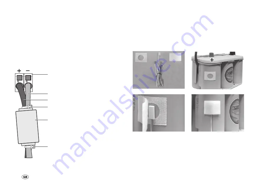
Snap ferrite
Install the snap ferrite near the device to achieve optimum
interference suppression. To this end, place the positive and
negative cables of the 12 V connections into the open ferrite,
close the snap ferrite and apply pressure until the lock en-
gages. Secure the snap ferrite using cable bands in front and
behind the ferrite.
1 Cage tension spring clamps
2 Negative charger cable blue
3 Positive charger cable red
4 Cable bands
5 Snap ferrite
2
3
4
4
5
1
Battery
Battery
Fig. 3: Snap ferrite
Temperature sensor
Attach the temperature sensor supplied to the battery casing,
near the positive terminal. To do this, remove the protective
film from the self-adhesive Velcro strip (with the recess) and
press this firmly onto the desired position on the battery. Posi-
tion the sensor in the middle of the recess and fix it in place
with the second Velcro strip. Connect the cable of the tem-
perature sensor to the temperature sensor connection of the
device (2-pole connection).
Fig. 4: Assembly of the temperature sensor
Battery type changeover switch
Set the battery type (liquid electrolyte or Gel / AGM) of your
battery on the battery switchover.


