6
7
5|
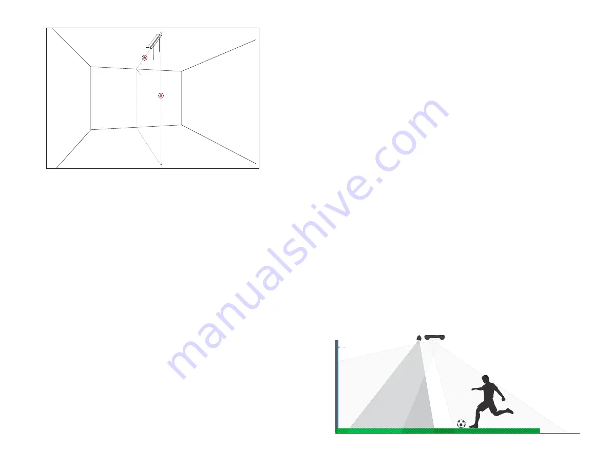
Attach the light track to the ceiling between the two marks, following
the instructions included with the light track.
• If mounting directly into a wooden stud, use the wood screws.
• If mounting into drywall, use the self-drilling drywall anchors.
6|
Use a Phillips screwdriver to remove one cap off of the end of the light track.
7|
Slide the E6 Interactive Sport Camera enclosure into the light track
using the two track guides on top of the enclosure.
IMPORTANT!
Make sure the end where the cables come out is facing the screen.
8|
Replace the light track cap.
9|
Plug in the USB extension cable’s female end to the camera USB, then plug
the USB extension cable’s male end into a USB 3.0 port on the computer.
NOTE:
Handle the USB 3.0 Fiberoptic Cable with care as a bend or kink in the
cable will cause a signal degradation or complete loss of signal.
10|
Plug in the power cable and run both the power cable and USB cable
along the framing and to the computer.
MOUNTING WITH A UNIVERSAL PROJECTOR MOUNT:
1|
Measuring from the exact center of the screen, make a mark on the
ceiling at the distance you measured in Step 1,
less 1 ft
.
EXAMPLE:
If the ceiling height is 10 ft., make a mark at 9’. Centering the
universal projector mount on this mark will put the back end of the E6
Interactive Sports Camera in the correct position (the same distance from
the screen as from the floor).
Center Mark
2 ft.
SCREEN
2|
Attach the universal projector mount to the ceiling, following the
instructions included with the universal projector mount.
• If mounting directly into a wooden stud, use the wood screws.
• If mounting into drywall, use the self-drilling drywall anchors.
3|
Attach the E6 Interactive Sports Camera enclosure to the universal
projector mount, using the washers and 4M screws.
IMPORTANT!
If you have an overhead projector and will be attaching the E6
ISC to the projector mount, be aware that the E6 ISC may block the top portion
of the projected image on-screen. In this case, you must either switch to a Light
Track mount for the E6 ISC or lower the height of your projector.
4|
Plug in the USB extension cable’s female end to the camera USB, then plug
the USB extension cable’s male end into a USB 3.0 port on the computer.
NOTE:
Handle the USB 3.0 Fiberoptic Cable with care as a bend or kink in the
cable will cause a signal degradation or complete loss of signal.
5|
Plug in the power cable and run both the power cable and USB cable
along the framing and to the computer.
USING AN IR BOOSTER TO IMPROVE SHOT REGISTRATION
AND ACCURACY
The E6 ISC is designed to work well in relatively low light, so your space
should be lit just well enough for the ISC to see balls in the Floor Area
(between the Tee Position and screen)
, but not so bright that the ambient light
washes out the projected image on the screen. With a high ceiling or not
enough light, the ISC may have trouble tracking objects, in which case, you
may need an
IR BOOSTER
Add-On.
IMPORTANT:
When mounting the IR Booster, it must be installed high
enough so that the unit itself does not fall into the field of view of the
ISC screen-facing camera. In addition to mounting it as exemplified in
the diagram below, you can also check to see if it is appearing in the ISC
camera’s field of vision once you reach the configuration stage (later in this
manual) and make adjustments.
PLAY AREA
FLOOR AREA
SCREEN
Содержание E6 Interactive Sports Camera
Страница 1: ...INTERACTIVE SPORTS CAMERA MANUAL 3 0...
Страница 11: ...TRUGOLF TRUGOLF COM COM...


