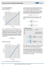
Supply/extract air tracking control
Fig. 10: Supply/extract air tracking control
1
Volume flow rate limit specification (q
vmin
and q
vmax
)
2
Room temperature controller (control signal for
supply air controller)
3
Actual value volume flow rate as 0–10 V DC signal
to the extract air controller
4
Actual value volume flow rate as 0–10 V DC signal,
e.g. to the central BMS
In individual rooms and closed-off office areas, where the balance between supply and extract air flow rate has to be
maintained. Otherwise, annoying whistling noises can occur at door gaps, and the doors can be difficult to open. For
this reason, the extract air should also have variable control in a VAV system.
The control signal from the room temperature controller is switched to the supply air controller in this example. The
actual value signal of the Easy controller for the supply air is then applied as a setpoint signal for the Easy controller
on the extract air (slave controller). As a consequence, the extract air always follows the supply air.
Setting for the slave controller in the simplest case (same VAV terminal units and dimensions):
q
vmin
0%
q
vmax
100%
When using different air terminal unit types or dimensions for tracking control, special setting instructions for q
vmin
and q
vmax
of the slave controller must be observed due to the different nominal volume flow rates.
Alternatively, the control signal of the room temperature controller can also be connected in parallel to the supply air
and the extract air controller. The limitation due to the technical data of the controller outputs (current) and the con-
troller inputs (input resistances) must be observed.
Structure and functional description
Operating modes > Operation with variable volume flow rate setpo...
Easy control component for VAV terminal units
15


