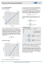
3.2 Product overview TVE type
Fig. 2: TVE basic unit with Easy controller
1
Easy controller
2
Damper blade
3
VAV terminal unit
4
Lip seal
5
Scale sticker for setting q
vmin
/q
vmax
(V
min
/ V
max
)
6
Release button and damper blade position indicator
7
q
vmin
potentiometer (V
min
)
8
q
vmax
potentiometer (V
max
)
9
Test push button and LED to display the operating
states, see table
10
Terminals
11
Service socket, not functional on Easy
12
Cover of the terminals
–
Adjustments sticker on VAV terminal unit (not pic-
tured)
Detection of operating states (LED) TVE type
LED flashing frequency
Meaning
Keine Spannungsversor-
gung
Controller not pre-set
Actuator overload
detected (block)
Positive pressure detected
on effective pressure
sensor
Synchronisation or test
mode activated
LED flashing frequency
Meaning
Setpoint value or override
control position not yet
reached (0.5 Hz flashes)
Control mode setpoint
value corrected
3.3 Position of the damper blade
The position of the damper blade corresponds to the
mark on the shaft and is thus recognisable from the out-
side.
Structure and functional description
Position of the damper blade
Easy control component for VAV terminal units
11


