


DL200X operating manual for external sensors
4
EN
5.2. Note at initial startup
b
After starting the device for the first time, the message “SET TIME”
appears on the display. However, no settings need to be made directly
on the device. The time synchronises itself with the PC time automatically when
connected to the SmartGraph software for the first time.
6. Operation
The PC software SmartGraph is the central configuration interface for your data
logger. All additional configuration and visualisation specifications can only be
set by software.
Basic settings can be directly configured with one-button operation by using
the mode selection button on your data logger.
You can restrict the one-button operation with the mode selection button from
your software if necessary (key lock). It is not possible to operate your data
logger with the mode selection button in this case.
6.1. Switching on and off
When current is being supplied, the data logger cannot completely switch off,
but can only be set to an operating mode with minimal energy consumption
(M1). In this mode, measured value detection, measured value display and data
recording are inactive. An overview of the four various operating modes is pro-
vided in the next chapter.
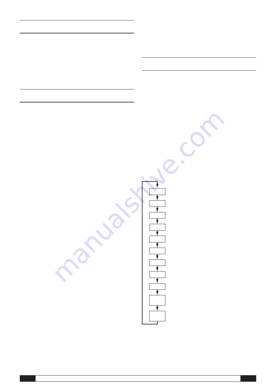
6.2. Basic settings and operating modes
Eleven basic settings can be configured by using the mode
selection button. These include the four various operating
modes, the network function, a global reset of settings, the
acoustic function and various settings for configuring external
sensors.
Briefly pressing the mode selection button changes to the
current setting level.
Briefly pressing the mode selection button allows navigation
through the individual setting modes.
Each chosen mode is shown for four seconds and
can be selected.
Within this time, the mode marker flashes in the bottom left
corner of the display (M1, M2, M3, M4, M51, M52, M53, M6x,
M7x, M81 (An0), M81 (An1)).
Pressing the mode selection button for 1 second confirms
your selection.
The data logger then changes to the selected mode.
If no selection is confirmed within the four second period, the
setting level is left and the display returns back to the original
mode without making changes.
* This function is only available if a BUS sensor has already
been registered (M61).
M81
An 0
M1
M2
M3
M4
M51
M52
M53
M6x
M81
An 1
M7x*
4. Scope of supply
The following components are included in the standard scope of supply:
•
Data logger
•
USB connection cable
•
CD-ROM with operating manual, SmartGraph software
and software manual
•
4 x AA batteries
•
Factory certificate
5. Preparation before starting
5.1. Software
5.1.1. Installation conditions
To configure your data logger and read the recorded measured values, the
SmartGraph software must be installed on a PC with the following minimum
requirements.
Supported operating systems:
•
Windows XP from Service Pack 3 (32 bit or 64 bit version)
•
Windows Vista (32 bit or 64 bit version)
•
Windows 7 (32 bit or 64 bit version)
Hardware requirements:
•
Processor speed: 1 GHz, minimum
•
CD-ROM drive
•
USB or network connection RJ45
•
512 MB RAM, minimum
•
4 GB of free hard disk space, minimum
•
Adobe Acrobat Reader software
5.1.2. Installation of the SmartGraph software
Insert the CD-ROM into your PC drive and install the software by following the
instructions in the installation wizard.
5.1.3 Preparing data logger configuration
If necessary, connect the external sensors which are needed for detecting
measured values to the external connections of your data logger.
Information about connecting and configuring suitable sensors is provided
in chapters 7 and 11. Follow the instructions in chapter 7 for connecting ex-
ternal sensors and then continue with startup.
Afterwards, connect the data logger to your PC via the USB cable provided in
the scope of supply. The measuring device is automatically detected by the
SmartGraph software.
Alternatively, you can configure your data logger via a LAN connection over
your local network if the network function is enabled. Further information about
the network function is provided in chapter 6.2.2.
Start the SmartGraph software. The program automatically detects the connected
data logger and adds it to the list of available data loggers. The data logger can
now be configured via the software.
Further detailed information about using the software is provided in the
software manual which you can open from the help function of the Smart-
Graph software.


