Aluminum2
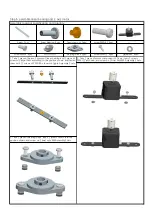
PM4*20
2-M3Hole on the lateral
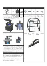
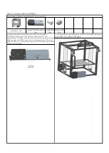
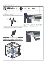
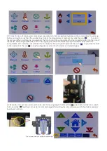
2. Will the Z axis of the carriage motor board ship nut to adjust, and put the
Z axis carriage in graphical position within the aluminum 2, here is a hole
on the outside of the M3 will be polished rod with aluminum 2 hole
alignment, with 20 PM4 * of the aluminum 2 hole above the screw through
the component, connected to the polished rod M4 screw hole, using PM4 *
20 screws through the aluminum 2 hole under its component, connected to
the M4 screw hole position.As shown in the figure;Turn the screw rod, slide
the cross plate assembly and the bearing seat to the top, lock the four
screws PM4*20 inside the aluminum profile 2 up and down of the assembly,
then lock the boat nut on the bearing seat, and then lock the two meter
screws on the bearing seat.Turn the screw and drop the cross plate
assembly to make sure it is flexible.Otherwise, please loosen the screw and
adjust it again.Finally, lock the 4 meter screws on the coupling and the boat
nut screws on the motor board.Turn the screw again to make sure that the
board slides up and down smoothly.
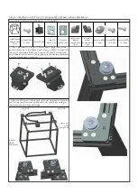
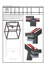
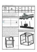
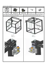
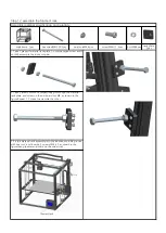
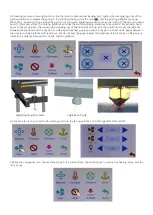
3. Repeat step 2 to assemble another z-axis slide carriage, as
shown in the figure.
Note: when the screw rod is assembled, the tail is about 3mm
inside than the polished rod.
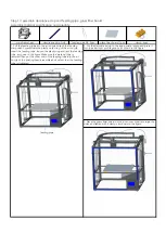
bearing block
components
2pcs
Polished rod
Φ8*528
4pcs
screwsPM4*
20 8pcs
Lead
screwT8*453
2pcs
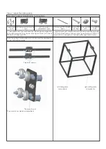
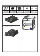
Step 7: assemble Z axis components
Assembly material specification and quantity:
beam
component
2pcs
frame 1pcs
Z axis motor bracket 2pcs
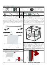
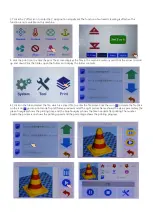
1. Take 1 piece of motor bracket of Z axis, insert the polished rod
into the acrylic plate hole of the motor bracket, and do not
protrude, as shown in the figure. Then, insert the cross plate
components into the second polished rod, and connect the screw
rod through the screw nut to the coupling hole of the
motor.Assemble a total of 2 sets --Z axis sliding rack.
3mm
Содержание X5S 2E
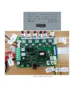
Страница 16: ...Wiring diagram of main board ...


