background image

5

A1

B1

S1

S2

S3

S4

S5

B2

B3

B4

B5

N1

A2

A3

A4

A5

A6

C1

C2

4 – Mounting

4-1 Unpacking

  Read Section 2 – Important Safety Instructions Before Mounting  

Warning: The UPS system is very heavy—be careful when moving or lifting it.

Remove the protective foam and unwrap the unit. Inspect the unit carefully prior to installation. If anything appears to be damaged, contact Tripp 
Lite for service. Retain the packing materials for future use.

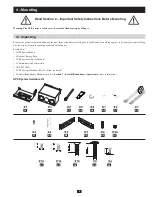
Packing List:
•  1 UPS Power Module
•  1 External Battery Pack
•  1 UPS System Owner’s Manual
•  1 Communication Software Kit
•  1 RS-232 Cable
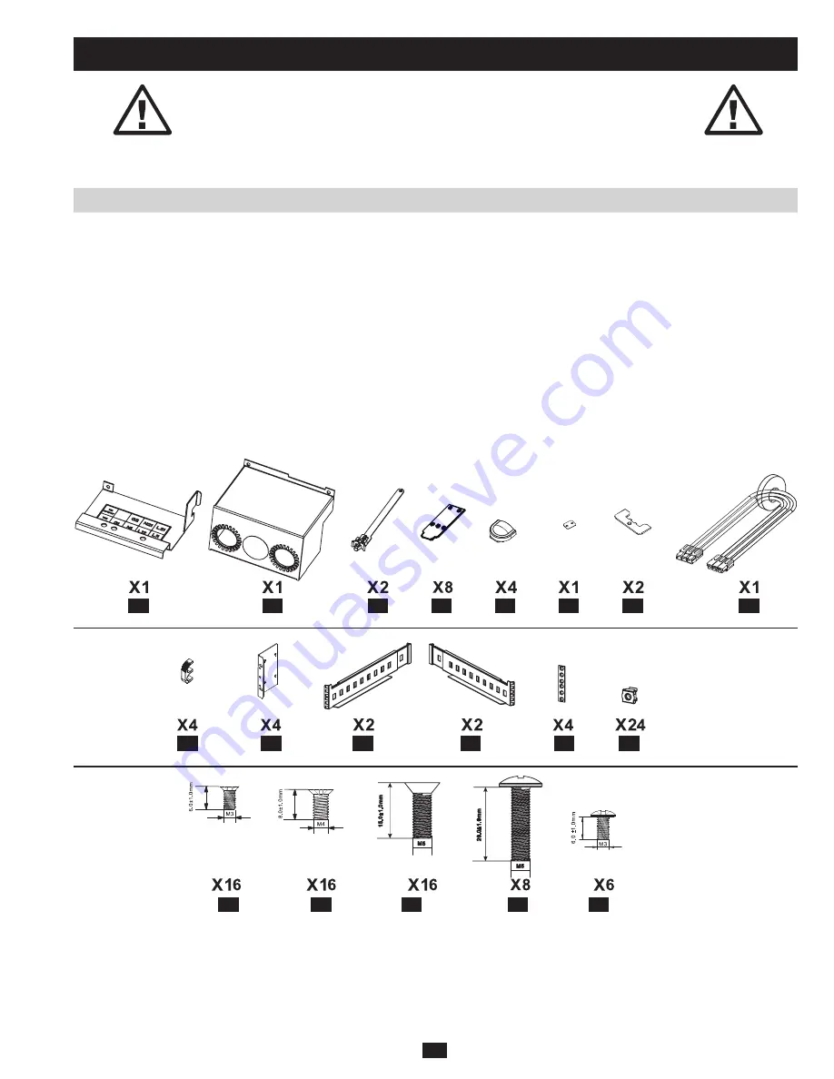
•  1 UPS System Hardware Kit (See below for detail.)
•  1 Parallel Redundancy Hardware Kit (See 

Section 7 – Parallel Redundancy Operation

 for more information.)

UPS System Hardware Kit

Содержание SmartOnline SU10KRT1X

Страница 1: ...Mounting 5 4 1 Unpacking 5 4 2 Placement 6 4 3 Mounting Rack 6 4 4 Mounting Tower 7 5 Wiring 8 5 1 Wiring Preparation 8 5 2 Terminal Block Diagram 8 5 3 Electrical and Cable Data 8 5 4 AC Input Output...

Страница 2: ...tilation openings of the UPS system or otherwise impede the airflow from the front to the rear of the UPS system Do not place any object on the UPS system especially containers of liquid Spilling liqu...

Страница 3: ...damage the UPS system and create a risk of personal injury and property damage Wiring should be performed by trained qualified electricians only Battery Warnings Allow batteries to charge uninterrupt...

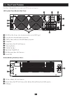
Страница 4: ...Note Remove the network card in order to use the RS 232 port B Settings Switch for Parallel Redundancy Operation C CAN Bus Connection Ports for Parallel Redundancy Operation D Cooling Fans E External...

Страница 5: ...unit Inspect the unit carefully prior to installation If anything appears to be damaged contact Tripp Lite for service Retain the packing materials for future use Packing List 1 UPS Power Module 1 Ext...

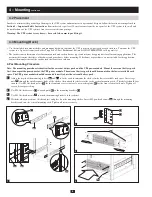
Страница 6: ...tact the manufacturer of the rack or rack enclosure for a solution 4 Post Mounting Procedure Note The mounting procedure is identical for the external battery pack and the UPS power module Mount the e...

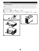
Страница 7: ...ition Pull the panel out slightly rotate it and push it back into place Tower Mounting Procedure 1 Use M4 flat head screws S2 to attach covers A5 to four of the tower feet A4 2 Use M3 flat head screws...

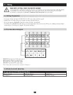
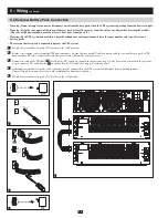
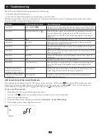
Страница 8: ...y pack Mark all cables according to their correct purpose polarity phase and diameter Review the diagram in Section 5 2 to familiarize yourself with the terminal block Consult the table in Section 5 3...

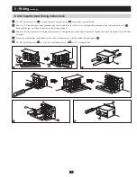
Страница 9: ...eves through the knockouts in the terminal block cover A2 Each input output wire should terminate with a ring terminal 3 Connect the ring terminal for each input output cable to the appropriate input...

Страница 10: ...system 1 Switch the external battery pack s DC breaker to the OFF position 2 Remove the terminal covers from the UPS power module s external battery pack DC cable connector and the external battery pa...

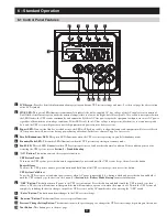
Страница 11: ...in economy mode 6 Fault LED This red LED illuminates when UPS system experiences a fault or other abnormal condition If the condition persists after restarting the UPS system refer to Section 9 Troubl...

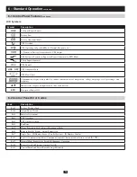
Страница 12: ...f temperature voltage amperage level percentage and frequency Indicates the category being measured line load battery EPO Emergency Power Off Code Description Er05 Battery Weak or Dead Er06 Output Sho...

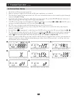
Страница 13: ...and the battery charger begins to charge the external battery pack 8 Press the ON button for approximately 3 seconds then release it The UPS will beep twice and the LCD screen will change from B to C...

Страница 14: ...elapsed you will need to repeat the previous step 5 The UPS system will run a self test and display H again Battery mode startup is successful and connected equipment will operate until the battery i...

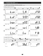
Страница 15: ...tely three seconds until the buzzer sounds twice then release the buttons Except for buzzer Q1 Q2 and self test R1 R2 all other default settings may now be changed by pressing the Previous Change Sett...

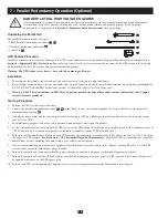
Страница 16: ...upply circuit is securely grounded Start up Procedure 1 Position the UPS systems as specified above 2 Connect the parallel communication cables C1 C2 to the Ring loop at a maximum length of 7 m Secure...

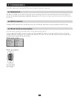
Страница 17: ...rting the EPO terminals activates the EPO emergency power off function which provides emergency shutdown of the UPS system Note The network card must be removed in order to use the UPS system s RS 232...

Страница 18: ...t LED Er16 Er27 All parallel UPS parameters except ID number must be same Adjust the parameters Fault LED Er21 Reconnect the RJ45 cable or set a UPS with ID 1 Fault LED Other Error Code Have a qualifi...

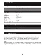
Страница 19: ...tility power source Next disconnect all equipment The UPS system must be stored in a clean secure environment with a temperature less than 40 C and a relative humidity less than 90 non condensing Note...

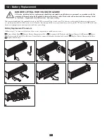
Страница 20: ...he batteries are designed for hot swap replacement i e replacement while the UPS system is in ON mode but some qualified service personnel may wish to put the UPS system in OFF mode and disconnect equ...

Страница 21: ...cific legal rights and you may have other rights which vary from jurisdiction to jurisdiction Tripp Lite 1111 W 35th Street Chicago IL 60609 USA WARNING The individual user should take care to determi...

Отзывы: