background image

6

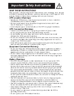
This multi-colored light displays 4 separate UPS load conditions.
It will turn from green (low) to yellow (medium) to red (high) as you
connect equipment to show you the load level your UPS is support-
ing. When the light is red your UPS is supporting a load above 85%
of its capacity. If the red light begins flashing, your UPS is severely
overloaded. Remove overload immediately until light stops flashing.

Other UPS Features

AC Receptacles

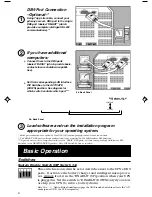
The receptacles provide your connected equipment with AC line
power during normal operation and battery power during black-
outs and brownouts. They also protect your equipment against
damaging surges and line noise. You can remotely reboot con-
nected equipment by turning all of the receptacles OFF and ON at
once using Tripp Lite UPS software. Select models, however,
feature unique “Remote Reboot Outlets” (identified on the back
panel of your UPS) which allow you to use Tripp Lite UPS software
to remotely reboot equipment connected to these outlets 

without

interrupting power to equipment connected to the other outlets

.* See

software instructions for details.

* Note: constant power is available at the Remote Reboot Outlets (and all other outlets)
unless controlled through Tripp Lite UPS software.

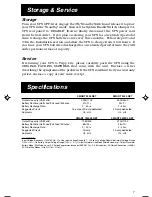
“SMART” RS-232 Port

The RS-232 port connects your UPS to any workstation or server.
Use with Tripp Lite software and #73-0743 cable to monitor and
manage network power and automatically save open files and shut
down equipment during a blackout. This port uses RS-232 com-
munications to transmit UPS and power conditions (Pin 7 =
Transmit; Pin 8 = Common; Pin 9 = Receive). Contact Tripp Lite
Customer Support for more information and a list of available
SNMP, network management and connectivity products.

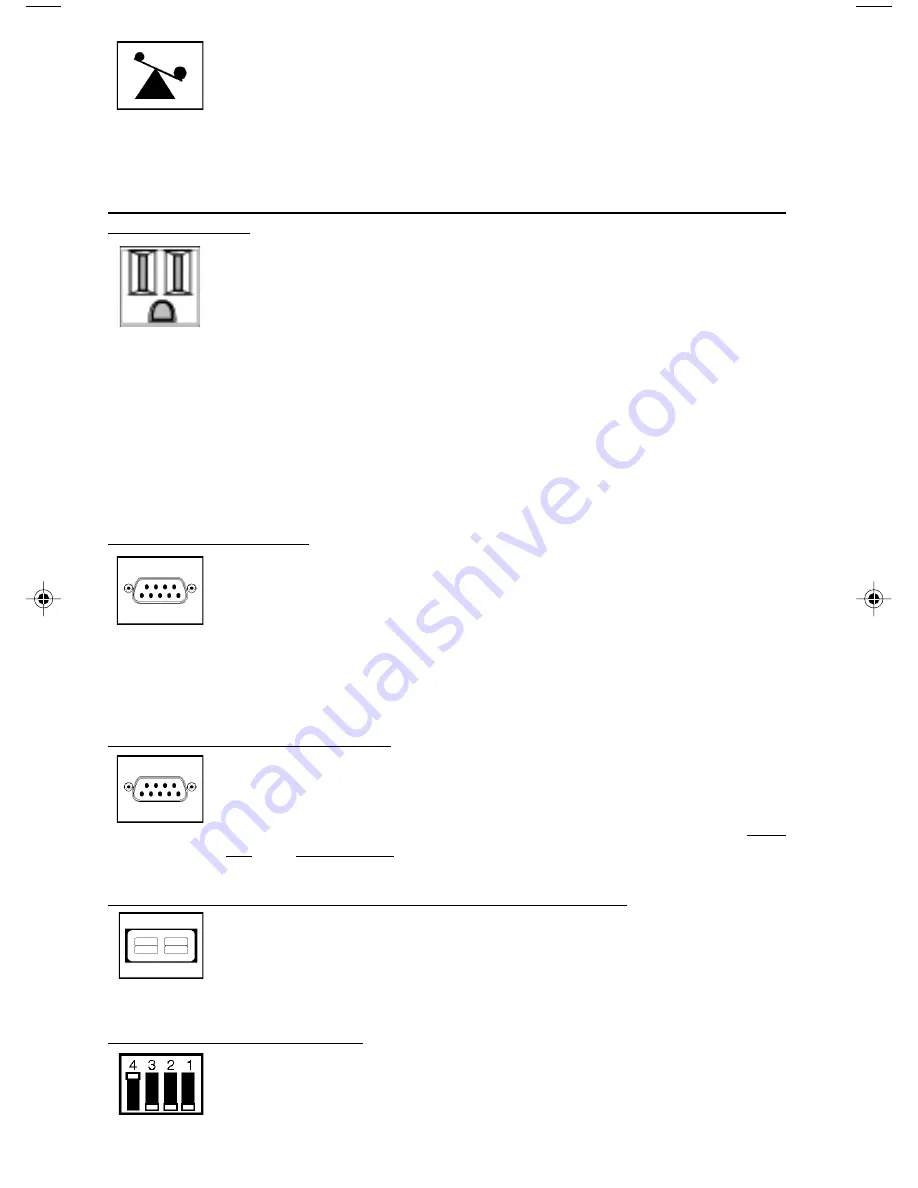
“BASIC” Contact-Closure Ports

The contact-closure ports connect your UPS to any workstation or
server. Use with Tripp Lite software and #73-0724 cabling to
automatically save open files and shut down equipment during a
blackout. This port sends contact-closure signals to indicate line-
fail and low-battery status. Contact Tripp Lite Customer Support
for more information.

External Battery Connector (available on select models)

Use this to connect additional Tripp Lite battery packs for addi-
tional runtime. Refer to the label next to the connector for
appropriate Tripp Lite battery pack to connect. Refer to instruc-
tions available with the battery pack for complete connection
information and safety warnings.

LAN Interface DIP Switches

DIP Switches #1 and #2 activate or deactivate remote shutdown
through the “BASIC” Contact-Closure Ports. See “DB9 Port Con-
nection” on page 4 for which switch controls which port. Note: DIP
Switch #3 has no function. DIP Switch #4 serves as
the UPS’s “System Enable Switch.”

9811198  SmartPro NET & SmartPro XC Owners Manual.p65

5/17/00, 10:57 AM

6

Содержание SMART 1250XL NET

Страница 1: ...th Street Chicago IL 60609 USA Customer Support 773 869 1234 www tripplite com Owner s Manual SmartPro NET SmartPro XL 1250 3000 VA Intelligent Network UPS Systems 120V ESPAÑOL p 8 FRANÇAIS p 15 Installation p 3 4 Basic Operation p 4 6 Storage Service p 7 Specifications p 7 Safety p 2 Warranty Insurance p 6 ...

Страница 2: ...antly alter the performance of a life support device Do not connect surge suppressors or extension cords to the output of your UPS This might damage your UPS and will void both the surge suppressor and UPS warranties Battery Warnings Your UPS does not require routine maintenance Do not open your UPS except to replace batteries There are no user serviceable parts inside Battery replacement should b...

Страница 3: ...he battery charger and microprocessor The XXX light will flash until you engage the ON Standby Switch to activate the ON mode Engage the momentary ON Standby Switch UPS front panel and release it to activate the ON mode and supply power to the UPS receptacles See Figure 2 3 2 1 DB9 Port Connection Optional On Next Page Figure 2 ON Standby Switch Figure 1 DIP Switch 4 System Enable Switch ENABLE DI...

Страница 4: ...232 communications If you have additional computers Connect them to the DB9 ports labeled BASIC which provide basic contact closure shutdown capabili ties Set their corresponding LAN Interface DIP Switches to the ACTIVATE DOWN position See diagram for which switch controls which port Serial port connections are optional Your UPS will function properly without these connections The SMART DB9 port i...

Страница 5: ...icator Lights All Indicator Light descriptions apply when the UPS is plugged into a wall outlet and turned ON This green light will shine constantly to indicate AC power is available at the receptacles It will flash to indicate AC power is not available See System Enable Switch and ON Standby Switch descriptions above This multi colored light displays 7 separate UPS battery charge conditions It wi...

Страница 6: ... port connects your UPS to any workstation or server Use with Tripp Lite software and 73 0743 cable to monitor and manage network power and automatically save open files and shut down equipment during a blackout This port uses RS 232 com munications to transmit UPS and power conditions Pin 7 Transmit Pin 8 Common Pin 9 Receive Contact Tripp Lite Customer Support for more information and a list of ...

Страница 7: ...toms of the problem If the UPS is within the 2 year warranty period enclose a copy of your sales receipt SMART 2200 NET SMART 3000 NET Output Capacity VA Watts 2200 1700 3000 2400 Battery Runtime Half Load Full Load Minutes 27 11 23 7 Battery Recharge Rate 2 4 hrs 2 4 hrs Suggested Circuit 15 amp or 20 amp dedicated 30 amp dedicated Approvals UL cUL UL cUL SMART 1250XL NET SMART 2200XL NET Output ...

Страница 8: ...1111 W 35th Street Chicago IL 60609 USA 773 869 1234 USA 773 869 1212 International www tripplite com ...

Отзывы: