Trident FOAMATE 2.1 Скачать руководство пользователя страница 3

215-293-0700 

7


215-293-0701

[email protected]

3

Technical Manual

Class B Foam System

Installation Instructions

Eductor 

(

Please refer to the 

Plumbing Diagram

Figure 4

 on 

Page 6

)

Mount the eductor in a 2" 

[50 mm] 

diameter line from the discharge side of the fire pump with a 2" 

[50 mm] 

ball shut-off valve upstream 

of the eductor. The discharge side of the eductor is plumbed with 2" 

[50 mm] 

piping back to the suction side of the fire pump. Observe 

the flow direction arrow on the eductor for proper placement. 

Foam Concentrate Metering Valve

A 2" metering valve can be mounted to an enclosed pump panel or directly into the piping with access to the pump operator. If mounted 
to an enclosed pump panel, piping connections to the valve must be properly supported – see valve mounting hole pattern  

Figure 3

 on 

Page 5

. Supply the inlet side of the metering valve with 2" 

[50 mm] 

plumbing from the foam concentrate tank. This line 

must include a 2" 

[50 mm] 

foam tank ball shut-off valve. 2" 

[50 mm] 

plumbing connects the discharge side of the metering valve to the 

eductor. Details of the metering valve internals are shown 

Figure 5

 on 

Page 9

This Line Must Include a 2"


[50 mm] 

Check Valve (supplied 

with the kit) to prevent back flow of water to the foam concentrate tank.

NOTE

: The swing check valve must be mounted in a horizontal position and in the correct direction for proper operation.

External Foam Concentrate Connection

A 2" 

[50 mm] 

valved hose connection can be provided at the pump panel to allow an external foam concentrate supply from drums, pails, 

etc. See 

Page 7

 for optional auxiliary foam concentrate pickup hose and pickup tubes.

Flushing Piping

Piping of 2" 

[50 mm] 

diameter is to be installed between the water inlet connection of 

the eductor and foam concentrate inlet of the metering valve as a means to flush both 
the metering valve and eductor after each use. This plumbing must include a 2" 

[50 

mm] 

ball shut-off valve.

Schematic/Instruction Chart

A backing plate is supplied for the schematic/instruction plate and must be mounted in 
close proximity to the foam metering valve.
Refer to 

Figure 2 

on

 Page 5

 for the mounting hole dimensions.

Plumbing Requirements


„

NOTE

: The design of the Metering Valve and Eductor are not intended to support 

the weight of the 2" 

[50 mm] 

plumbing. Piping to and from the Eductor and Foam 

Metering Valve must be properly supported.


„

Foam metering valve and all of the 2" 

[50 mm] 

ball shut-off valves in the system 

must be accessible to the pump operator.


„

Refer to 

Figure 3

 on 

Page 5

 for the mounting hole dimensions for the 

Metering 

Valve


Backing Plate

.


„

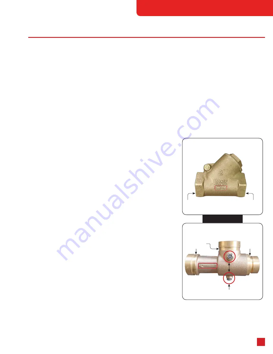
Observe that the cast in arrows in the red rectangles in 

Figure 1 

on the Check 

Valve and Eductor are installed in the manner as shown in the plumbing diagram 

Figure 4

 on 

Page 6

.


„

The eductor features two (2) 

1

4

" NPT pipe plugs shown in the red circles in 

Figure 

1

 for use as drain points based on the orientation of the eductor. All other plumbing 

connections on the eductor are VIC pipe grooved ends.

Plumbing Recommendations 

(Also Refer to top of 

Page 7

)


„

Install a valved direct water tank fill line to keep the on-board water tank filled 
from hydrant or nurse tanker. With this feature the foam system can be used 
continuously from the on-board water tank greatly simplifying the 5 PSI inlet pump 
pressure restriction.


„

Install a valved external auxiliary foam inlet connection at the pump panel to 
supplement the on-board foam tank. With this feature, using a pick-up tube, a different type of foam concentrate can be used from 
that of the on-board tank.  It also eliminates the need to fill the on board foam cell during an extended operation by supplying foam 
concentrate directly from containers on the ground. Also, with this auxiliary foam inlet and pick-up tube, foam system training 
can be done simply utilizing a container on the ground filled with water; operators can see how the system draws water based on 
different metering valve settings.

Figure 1

2" FNPT

[50 mm]

2" VIC

[50 mm]

1

1

2

" VIC

[38 mm]

1

4

" NPT

[7.1mm]

2" FNPT

[50 mm]

Содержание FOAMATE 2.1

Страница 1: ...Class B ATP Foam System FOAMATE 2 1 Technical Manual ...

Страница 2: ...d Foam Tank 4 Foam System Operating Procedures from External Auxiliary Foam Concentrate Source 4 General Operating Tips for ATP Foam Systems 4 Foam System Shutdown Instructions 4 Foam System Flushing Instructions 4 Schematic Instruction Plate Template 5 Metering Valve Dial Template 5 Piping Schematic 6 Benefits of an External Pickup Tube Enhancing Your Foam System 7 Model Numbers and Parts Listing...

Страница 3: ...ll shut off valve Schematic Instruction Chart A backing plate is supplied for the schematic instruction plate and must be mounted in close proximity to the foam metering valve Refer to Figure 2 on Page 5 for the mounting hole dimensions Plumbing Requirements NOTE The design of the Metering Valve and Eductor are not intended to support the weight of the 2 50 mm plumbing Piping to and from the Educt...

Страница 4: ...2 50 mm system flush valve must be closed 6 Open 2 50 mm external auxiliary foam concentrate inlet valve NOTE The foam system will work properly from draft or the on board water tank If operating from a pressurized water source hydrant or relay pumper maximum fire pump inlet pressure cannot exceed 5 PSI 0 35 BAR for proper foam system operation In the event of high fire pump inlet pressure install...

Страница 5: ...Metering Valve 1 2 11 2 x 2 Eductor 1 3 2 Brass Swing Type Check Valve 1 4 Schematic Instruction Plate 1 5 Backing Plate 1 FOAMATE 2 1 System Components With Ball Valves See Page 8 for Kit Part Numbers and Component Details Item Description Quantity 1 2 Foam Concentrate Metering Valve 1 2 11 2 x 2 Eductor 1 3 2 Brass Swing Type Check Valve 1 4 Schematic Instruction Plate 1 5 Backing Plate 1 6 2 Br...

Страница 6: ... On Board Water Tank Apparatus On Board Foam Tank All Foamate 2 1 Piping to be a Minimum of 2 ID All Piping To Be Supplied By System Installer Water Pump Three 2 Ball Valves Provided with Kits that include valves 2 Ball Valve available for Auxiliary Foam Inlet P N 30 058 0 Piping Schematic FOAMATE 2 1 Piping Schematic Shown below is the typical installation of the FOAMATE 2 1 ATP Foam Proportionin...

Страница 7: ...Concentrate Pickup Tube Assemblies ure 4 FOAMATE 2 1 ATP Auxiliary Foam Pickup Kits Part Description 10 010 1 2 x 10 Pickup Hose and Pickup Tube Without Ball Valve 10 010 2 2 x 10 Pickup Hose and Pickup Tube With Ball Valve Benefits of an External Pickup Tube Enhancing Your Foam System With a pick up tube the system can use either Class A or Class B foam that is a huge advantage in operation capab...

Страница 8: ...VIC Ends 1 02 028 2 Label Foamate 2 1 LPM Flow Rates 1 02 023 1 Label Foamate 2 1 Instruction 1 02 023 2 Backing Plate Label 1 30 064 0 2 FNPT Check Valve 1 31 014 4 Foamate 2 1 ATP System VIC Ends GPM Flow Rates With Ball Valves Part Number Description Qty 30 043 4 2 Metering Valve VIC Ends 1 31 005 0 11 2 x 2 Eductor VIC Ends 1 02 028 1 Label Foamate 2 1 GPM Flow Rates 1 02 023 1 Label Foamate 2...

Страница 9: ...ers Item Qty Part Description Material 1a 1 07 017 1 Body 2 Inch Foam Bypass Valve VIC Brass 1b 1 07 017 2 Body 2 Inch Foam Bypass Valve FNPT Brass 2 1 12 005 0 Cylinder 2 Inch Bypass Valve Brass 3 1 26 119 1 O Ring 119 EPDM 4 1 26 125 1 O Ring 125 EPDM 5 1 17 003 6 Slotted Spring Pin 1 8 x 3 4 Long Stainless 6 2 17 003 5 Slotted Spring Pin 1 8 x 1 2 Long Stainless 7 1 04 046 0 Retaining Ring Inte...

Страница 10: ...t procedures when doing any apparatus service 3 Foam tank shut off valve must be closed 4 Place metering valve in the closed position 5 Refer to exploded view of metering valve on Page 9 prior to metering valve disassembly Make note of all component positions and match mark all components during disassembly to maintain correct orientation during reassembly 6 Remove two 2 screws from metering valve...

Страница 11: ... 0701 sales tridentdirect com 11 Technical Manual Class B Foam System Installation Notes Record details of the installation on your Fire Truck Operating Notes Training notes on operation of the foam system on your Fire Truck ...

Страница 12: ...dentemergency GP Series Foam Pumps Other Foam System Products Model U Universal Mount Model H Hydraulic Mount Model M Bell Housing Mount Contact Us For Details On These And Other Foam System Products FOAMATE 2 1 Installed Trident Emergency Products LLC 2940 Turnpike Drive Suite 9 Hatboro PA 19040 USA 215 293 0700 Phone 215 293 0701 Fax sales tridentdirect com Email TridentDirect com FOAM PUMPS TM ...

Отзывы: