13
2-1
INTRODUCTION
The PORTA-TAC Crimper has been extensively redesigned. The re-design results
in additional logic functions being added to prevent possible malfunctions, while
at the same time reducing the overall number of components.
All logic, control and operating functions of the PORTA-TAC Crimper are
performed pneumatically, electrically or both.
The purpose of this Theory of Operation is to provide an overview of how the
PORTA-TAC operates such that a general understanding of the functions can be
achieved. In the event a PORTA-TAC is to malfunction, familiarity with its
operational sequences will greatly expedite corrective action.
System design is such that many events are sequential and, unless the PORTA-
TAC is positive a given event has properly occurred, subsequent events will not
occur. This design, in conjunction with high-tolerance machined components,
reduces significantly the possibility of initiating crimps on incorrect contacts, or
proceeding to crimp additional contacts if proper crimp tolerances are not being
achieved.
If the crimped contact/conductor is not removed after the crimping cycle is
complete, the PORTA-TAC will pause. The PORTA-TAC will remain in the
"pause" position until the contact/conductor is removed.
Please refer to Figure 2-1 while reading this Theory of Operation.
PNEUMATIC SUPPLY
Air pressure is supplied to the PORTA-TAC when the operator- controlled Sleeve
Valve (SV) is closed manually. Prior to closing the Sleeve Valve, the LAST
PART Switch (LP-l) should be in the OFF (up) position.
Electrical power is supplied to the PORTA-TAC via a small wall mount power
pack. Output from this power pack (12V DC) is switched on to the Controller
Card (CC-I) via Air Switch S-5.
Содержание PORTA TAC E Series
Страница 7: ...7 FIGURE 1 1 PORTA TAC CRIMPER FRONT VIEW ...
Страница 8: ...8 FIGURE 1 2 PORTA TAC CRIMPER WITH MAGAZINE ...
Страница 9: ...9 FIGURE 1 3 PORTA TAC CRIMPER SIDE VIEW ...
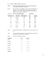
Страница 11: ...11 ...
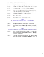
Страница 17: ...17 ...
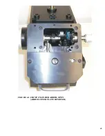
Страница 26: ...26 FIGURE 4 1 CRIMP CYLINDER ARBOR OPEN ARBOR COVER PLATE REMOVED ...
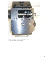
Страница 27: ...27 FIGURE 4 1 CRIMP CYLINDER ARBOR CLOSED ARBOR COVER PLATE REMOVED ...
Страница 30: ...30 FIGURE 4 3 CRIMP INSPECTION POINTS ...
Страница 31: ...31 FIGURE 4 4 IMPROPER CRIMPS ...
Страница 32: ...32 ...
Страница 37: ...37 CONDUCTOR STARNDS PROPER INDENTS VISIBLE ACCEPTABLE CRIMP BIRDCAGE UNACCEPTABLE CRIMP FIGURE 5 1 CRIMPS ...
Страница 40: ...40 FIGURE 6 1 PANEL COMPONENTS ...
Страница 41: ...41 FIGURE 6 2 CABINET COMPONENTS TRANSFER MECHANISM ...
Страница 44: ...44 FIGURE 6 3 INDENTER SYSTEM REPLACEMENT ...
Страница 45: ...45 ...
Страница 46: ...46 FIGURE 6 5 INDENTER REPLACEMENT ...
Страница 50: ...50 ...
Страница 53: ...53 ...


