12
1-3
OPERATOR TECHNIQUE
Crimp location on the contact and depth of crimp are entirely PORTA-TAC dependent.
The operator only need select (if applicable) the proper
"G"
dimension setting and
initiate the crimp cycle by inserting the conductor into the contact and depressing it by
applying slight pressure.
A conductor whose strands are not visible through the contact inspection hole (if
applicable) was probably caused
by an insufficient strip length or too Iowa pressure setting of the Transfer Tip Slide
Cylinder (refer to Section 6).
Operators usually get the "feel" of the machine within 15 minutes of use. Noise
generated by the device is minimal; operators have been observed to develop a rhythm of
insertion and withdrawal based on the unique sounds generated by the device. Crimp
rates exceeding 1800 crimps per hour have been attained.
Section V, Operating Procedures, gives detailed instructions to become familiar with the
equipment and operate it correctly and efficiently.
PORTA-TAC CRIMPER SPECIFICATIONS
PORTA-TAC crimps
most
shouldered and shoulder less contacts
Weight
Approx. 30 lb
Air
15 CFM at 85 PSIG
Input Air Connection
3/8"
Electric
110V 60 HZ ( 240V 50 HZ)
Dimensions
H = 14", W = 13", D= 20"
Contact Feed Rate
Approx. 1800/hr
Magazine Capacity
250 contacts
Contact Size Range
16g - 22g
Wire Gauge Range
16g - 26g
Содержание PORTA TAC E Series
Страница 7: ...7 FIGURE 1 1 PORTA TAC CRIMPER FRONT VIEW ...
Страница 8: ...8 FIGURE 1 2 PORTA TAC CRIMPER WITH MAGAZINE ...
Страница 9: ...9 FIGURE 1 3 PORTA TAC CRIMPER SIDE VIEW ...
Страница 11: ...11 ...
Страница 17: ...17 ...
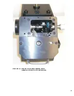
Страница 26: ...26 FIGURE 4 1 CRIMP CYLINDER ARBOR OPEN ARBOR COVER PLATE REMOVED ...
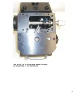
Страница 27: ...27 FIGURE 4 1 CRIMP CYLINDER ARBOR CLOSED ARBOR COVER PLATE REMOVED ...
Страница 30: ...30 FIGURE 4 3 CRIMP INSPECTION POINTS ...
Страница 31: ...31 FIGURE 4 4 IMPROPER CRIMPS ...
Страница 32: ...32 ...
Страница 37: ...37 CONDUCTOR STARNDS PROPER INDENTS VISIBLE ACCEPTABLE CRIMP BIRDCAGE UNACCEPTABLE CRIMP FIGURE 5 1 CRIMPS ...
Страница 40: ...40 FIGURE 6 1 PANEL COMPONENTS ...
Страница 41: ...41 FIGURE 6 2 CABINET COMPONENTS TRANSFER MECHANISM ...
Страница 44: ...44 FIGURE 6 3 INDENTER SYSTEM REPLACEMENT ...
Страница 45: ...45 ...
Страница 46: ...46 FIGURE 6 5 INDENTER REPLACEMENT ...
Страница 50: ...50 ...
Страница 53: ...53 ...


