16
2-4
Normal Operation (cont).
When the Transfer Arm reaches the vertical position, a limit switch (LS-l) is
engaged and the following events occur:
-Limit Switch sensor (S-2 ) is turned on
-High pressure is supplied to Slide Cylinder, allowing it to stay in the fully
extended position
-V-3 is deactivated closing funnels
-Index Cylinder (IC-l) is activated, advancing the magazine belt one
increment to deposit another contact in the Drop Tube.
If the contact exits the Drop Tube and seats properly in the Transfer Tip,
adequate vacuum will exist to switch on the Transfer Tip Sensor S-6. Supply
for Vacuum Sensor switch is provided by Vacuum Generator VG-l.
Note: If" a contact does not seat properly in the Transfer Tip, the cycle will
terminate until reset.
With S-6 turned on again, V-2 is turned off, allowing the Transfer Arm to
return to the "ready to crimp" position.
The PORTA-TAC is now ready to have another properly stripped conductor
inserted the wire funnel and commence another crimping cycle.
Prior to crimping the last conductor, the LAST PART Switch should be set to
the ON (down) position to prevent the magazine belt from advancing and
depositing another contact into the drop tube.
Содержание PORTA TAC E Series
Страница 7: ...7 FIGURE 1 1 PORTA TAC CRIMPER FRONT VIEW ...
Страница 8: ...8 FIGURE 1 2 PORTA TAC CRIMPER WITH MAGAZINE ...
Страница 9: ...9 FIGURE 1 3 PORTA TAC CRIMPER SIDE VIEW ...
Страница 11: ...11 ...
Страница 17: ...17 ...
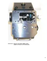
Страница 26: ...26 FIGURE 4 1 CRIMP CYLINDER ARBOR OPEN ARBOR COVER PLATE REMOVED ...
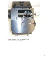
Страница 27: ...27 FIGURE 4 1 CRIMP CYLINDER ARBOR CLOSED ARBOR COVER PLATE REMOVED ...
Страница 30: ...30 FIGURE 4 3 CRIMP INSPECTION POINTS ...
Страница 31: ...31 FIGURE 4 4 IMPROPER CRIMPS ...
Страница 32: ...32 ...
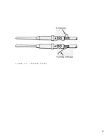
Страница 37: ...37 CONDUCTOR STARNDS PROPER INDENTS VISIBLE ACCEPTABLE CRIMP BIRDCAGE UNACCEPTABLE CRIMP FIGURE 5 1 CRIMPS ...
Страница 40: ...40 FIGURE 6 1 PANEL COMPONENTS ...
Страница 41: ...41 FIGURE 6 2 CABINET COMPONENTS TRANSFER MECHANISM ...
Страница 44: ...44 FIGURE 6 3 INDENTER SYSTEM REPLACEMENT ...
Страница 45: ...45 ...
Страница 46: ...46 FIGURE 6 5 INDENTER REPLACEMENT ...
Страница 50: ...50 ...
Страница 53: ...53 ...


