TRENDnet TEG-240WS Скачать руководство пользователя страница 16


25 

z


Monitor Load:

 To manually load the setting file of the 

Monitor List. 

z


Exit:

 To exit the Web Management Utility. 

In the 

“View TAB”

, there are view log and clear log function, this 

function will help you to show trap setting. 

z


View Log:

 To show the event of the Web Management Utility 

and the device. 

z


Clear Log:

 to clear the log. 

In the 

“Option TAB”

, there are Refresh Time function, this function 

helps you to refresh the time of monitoring the device. Choose 

15 

secs, 30 secs, 1 min, 2 min and 5 min

 to select the time of monitoring. 

In the 

“Help TAB”

, there is About function, it will show out the 

version of the Web Management Utility. 

Configuring the Switch 

The TEG-240WS 24-Port 10/100/1000Mbps Gigabit Ethernet Web 
Smart Switch has a Web GUI interface for smart switch configuration. 
The Switch can be configured through the Web Browser. A network 
administrator can manage, control and monitor the switch from the 
local LAN. This section indicates how to configure the Switch to 
enable its smart functions 


26 

Login 

Before you configure this device, note that when the Web Smart 
Switch is configured through an Ethernet connection, make sure the 
manager PC must be set on same the 

IP network

. For example, when 

the default network address of the default IP address of the Web Smart 
Switch is 

192.168.0.1

, then the manager PC should be set at 

192.168.0.x (where x is a number between 2 and 253), and the default 
subnet mask is 255.255.255.0. 

Open Internet Explorer 5.0 or above Web browser. 

Enter IP address 

http://192.168.0.1


(the factory-default IP address 

setting) to the address location. 


Figure 13. 

Or through the Web Management Utility, you do not need to 
remember the IP Address, select the device shown in the Monitor List 
of the Web Management Utility to settle the device on the Web 
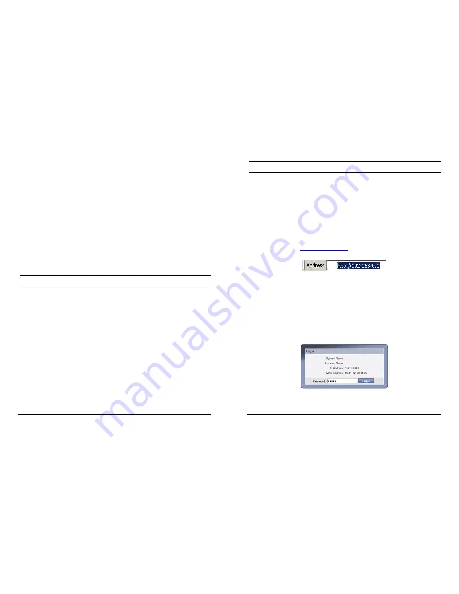
Browser. When the following dialog page appears, remain enter the 
default password 

"admin" 

and press Login to enter the main 

configuration window. 


Figure 14. Login 

Содержание TEG-240WS

Страница 1: ...quency energy and if not installed and used in accordance with this user s guide may cause harmful interference to radio communications Operation of this equipment in a residential area is likely to c...

Страница 2: ...ot compromised c Mechanical Loading mounting of the equipment in the rack should be such that a hazardous condition is not achieved due to uneven mechanical loading d Circuit Overloading Consideration...

Страница 3: ...m LEDs 15 1000BASE T Port 1 24 Status LEDs 16 Mini GBIC Port 23 24 Status LEDs 17 Configuration 19 Installing the Web Management Utility 19 Discovery List 20 Monitor List 21 ii Device Setting 23 Toolb...

Страница 4: ...10Mbps Ethernet network capabilities in a highly flexible package Purpose This guide discusses how to install your TEG 240WS 24 Port 10 100 1000Mbps Gigabit Ethernet Web Smart Switch Terms Usage In t...

Страница 5: ...perform 10 times the number of operations in the same amount of time 4 In addition the phenomenal bandwidth delivered by Gigabit Ethernet is the most cost effective method to take advantage of today a...

Страница 6: ...ired make routers relatively impractical Today switches are an ideal solution to most kinds of local area network congestion problems 6 VLAN Virtual Local Area Network A VLAN is a group of end station...

Страница 7: ...Supports IEEE 802 1p Priority Queues Supports Static Port Trunk Supports Jumbo Frame Supports Broadcast Storm Control Supports Port Mirroring Supports Port Setting for Speed Flow control Easy configur...

Страница 8: ...installing consider the following pointers Install the Switch in a fairly cool and dry place See Technical Specifications for the acceptable temperature and humidity operating ranges Install the Switc...

Страница 9: ...Ethernet that runs both in half and full duplex mode and 1000Mbps Gigabit Ethernet runs in full duplex mode using four pairs of Category 5 cable These 1000BASE T ports are Auto MDI type port The Switc...

Страница 10: ...e When the port is set to Forced Mode the Auto MDI MDIX will be disabled 14 Mini GBIC Slots Port 23 24 The Switch is equipped with two combo mini GBIC ports supported optional 1000BASE SX LX mini GBIC...

Страница 11: ...f The CPU is not working 16 1000BASE T Port 1 24 Status LEDs Link ACT Link Activity On When the Link ACT LED lights on the respective port is successfully connected to an Ethernet network Blinking Whe...

Страница 12: ...ansmitting or receiving data on the Gigabit Ethernet network Off Fiber line or mini GBIC module is not installed Speed Green When the Speed LED lights green the respective port is connected to a 1000M...

Страница 13: ...Follow the on screen instructions to install the utility 4 Upon completion go to Program Files web_management_utility and open the Web Management utility Figure 7 20 Figure 7 Web Management Utility Th...

Страница 14: ...e DHCP status of the device z Location Shows where the device is located z Trap IP Shows the IP where the Trap to be sent z Subnet Mask Shows the Subnet Mask set of the device z Gateway Shows the Gate...

Страница 15: ...the password needed in the dialog box and press Set button to proceed the password change immediately Figure 11 Password Change 24 Firmware Upgrade When the device has a new function there will be a n...

Страница 16: ...control and monitor the switch from the local LAN This section indicates how to configure the Switch to enable its smart functions 26 Login Before you configure this device note that when the Web Sma...

Страница 17: ...The Link Status in the screen will show the connection speed and duplex mode else this dialog box will show Down when the port is disconnected Figure 17 Port Setting Note The priority of Gigabit Fiber...

Страница 18: ...ement by allowing users to move devices to a new VLAN without having to change any physical connections The IEEE 802 1Q VLAN Configuration page provides powerful VID management functions The original...

Страница 19: ...g Name and select the ports to be trunked together and click Apply to activate the selected Trunking groups Figure 23 Trunk Configuration Be sure that the selected trunk setting port must connect to t...

Страница 20: ...t and for packets that are untagged the switch will assign the priority in the tag depending on your configuration Figure 25 IEEE 802 1p Default Priority Setting 34 Broadcast Storm Control Setting The...

Страница 21: ...are two ways for the switch to attain IP Static and DHCP Dynamic Host Configuration Protocol When using static mode the IP Address Subnet Mask and Gateway can be manually configured When using DHCP mo...

Страница 22: ...ber Port Event Monitoring the Fiber port status Link Up Link Down a trap when there is linking status happens in mini GBIC connection Twisted Pair Port Event Monitoring the twisted pair port status Li...

Страница 23: ...eset the details displayed 40 To view the statistics of individual ports click one of the Port ID as Figure 33 Figure 33 Port Statistics Factory Reset The Factory Reset helps you to reset the device b...

Страница 24: ...sword will not be erased Firmware Upload The Firmware Upload helps you to backup or upload firmware from to the Switch Once you need to backup the current firmware of the Switch press the Backup butto...

Страница 25: ...4 pair UTP Cat 5 up to 100m Fiber module Mini GBIC Fiber module LC Type Cable Number of Ports 24 10 100 1000Mbps Auto MDIX RJ 45 ports 2 Combo mini GBIC slots Physical and Environmental AC inputs 100...

Страница 26: ...ARRANTED ABOVE THE CUSTOMER S SOLE REMEDY SHALL BE AT TRENDNET S OPTION REPAIR OR REPLACEMENT THE FOREGOING WARRANTIES AND REMEDIES ARE EXCLUSIVE AND ARE IN LIEU OF ALL OTHER WARRANTIES EXPRESSED OR I...

Страница 27: ...47...

Отзывы: